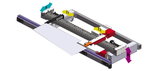
The functions defined by each axis are shown in the table below:
| Axis Name | Axis function description |
| Y1 | Electro-hydraulic synchronous full-closed loop control axis of left cylinder |
| Y2 | Electro-hydraulic synchronous full closed-loop control axis of right cylinder |
| X | Backgauge semi-closed loop mechanical motion axis, if equipped with X1 axis, this is the left finger control axis |
| X2 | The finger control axis on the right side of the backgauge |
| R | Vertical lift control axis for rear finger |
| Z1 | The mechanical axis that the left finger moves left and right on the stop beam |
| Z2 | The mechanical axis that the right finger moves left and right on the stop beam |
| V | crowning control axis |
In the CNC bending machine, the motion and functional components controlled by the CNC system can be referred to as CNC axes for short. In general, the name of the CNC axis name is based on the position of each axis in the machine tool in accordance with the coordinate system, while other motion and functional components are named according to conventional usage or international standards. Then, the configuration of several axes for CNC bending machine is generally based on the process requirements of the user to process the workpiece.
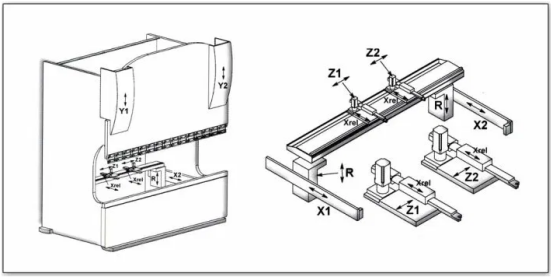
Y1, Y2 axis
The Y1 and Y2 axes are the synchronous axes of the two left and right cylinders that control the slider, and also control the bending depth (bending angle) of the slider. The two axes are collectively called the Y axis. As shown in the figure: Y1-REF is the reference point value of the left cylinder, this value is the distance from the zero point line to the zero pulse point of the left grating ruler. Y2-REF is the reference point value of the right cylinder, this value is the distance from the zero point line to the zero pulse point of the right grating ruler. Since the installation of the grating ruler cannot ensure that the zero pulse points on the left and right sides are on the same straight line parallel to the zero point line of the Y-axis coordinate, in order to keep the slider horizontal when the slider moves to the same programmed position of Y1 and Y2, Y1-REF , The value of Y2-REF is different.
Backgauge X axis
The X axis of the back gauge is a numerical control axis that controls the front and back movement of the back gauge. This axis is driven by a servo motor, and the encoder feeds back the front and back position of the gauge.
Backgauge R axis
The backgauge R axis is a numerical control axis that controls the up and down movement of the backgauge. This axis is driven by a servo motor, and the encoder feeds back the up and down position of the backgauge.
Backgauge Z1, Z2 axis
The Z1 axis is the mechanical axis that the left stop finger moves left and right on the stop beam. The right side stop of Z2 axis refers to the mechanical axis that moves left and right on the stop beam.
Multi-axis selection
3+1 Axis:Y1,Y2,X,+V
4+1 Axis:Y1,Y2,X,R,+V
6+1 Axis:Y1,Y2,X,R,Z1,Z2,+V
8+1 Axis:Y1,Y2,X1,X2,R1,R2,Z1,Z2,+V