


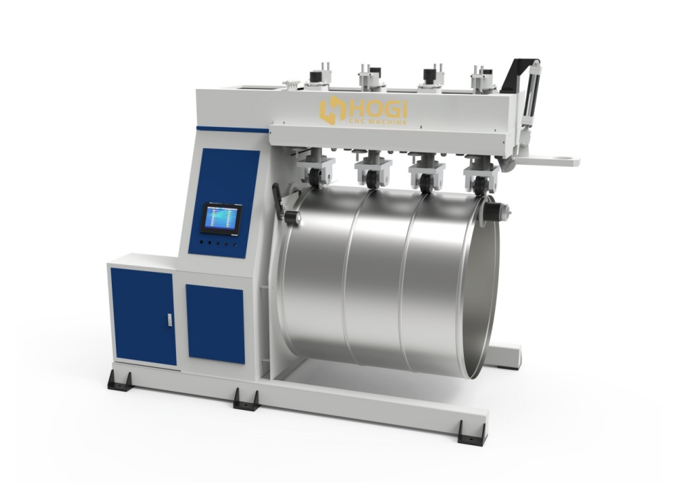
HOGI Round duct pipe Stiffener machine Reinforcements ribs Forming machine
HOGI Duct stiffeners are an important structural measure used in ventilation and air conditioning projects to enhance the structural rigidity of metal ducts and prevent them from deforming under positive or negative pressure.
In the fabrication and installation of metal ductwork, stiffeners (also known as reinforcements) are a critical process used to increase the strength of the duct walls and prevent periodic flutter and noise caused by airflow pressure differentials (commonly known as “bulging” or “duct rumbling”).
1. Structure and Manufacturing Methods (Form & Types)
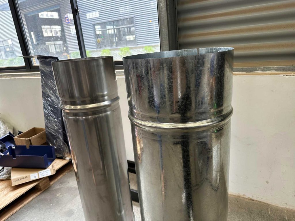
Beaded / Grooved Stiffeners: The most common type, created by pressing continuous raised and recessed ridges directly onto the duct sheet metal using a beading machine.
Z-Shaped / Hat-Shaped Stiffeners: External profiles such as Z-shaped, hat-shaped (Ω-shaped), or angle steel are attached to the outer wall of the duct.
Internal Tie Rods: Galvanized pipes or bolts are used inside the duct to provide span support; this method is commonly used for extra-large ducts.
Standing Seam Stiffener: Utilizes the duct’s own standing seam joint structure to provide longitudinal or circumferential reinforcement.
2. Processes and Processing Equipment (Equipment & Craftsmanship)
Duct Beading Machine / Grooving Machine: Machinery specifically designed to roll stiffeners onto sheet metal.
5-Line Beading / Multi-Line Beading: A common process for continuously pressing multiple parallel stiffeners.
TDF/TDC Flange & Beading: In fully automated duct production lines (such as 5-line or 7-line machines), beading and flange forming are completed simultaneously.
Stiffener Pitch / Spacing: The distance between stiffeners; standard requirements typically range from approximately 150\text{mm} to 300\text{mm}.
Bead Depth: The height of the raised and recessed sections of the stiffener groove; typically 3\text{mm} to 5\text{mm}.
3. Technical Standards and Design Specifications
GB 50243 (Chinese National Standard): *Code for Acceptance of Construction Quality of Ventilation and Air-Conditioning Engineering*, which sets strict requirements regarding the maximum length of the longer side of a duct that requires reinforcement (e.g., rectangular ducts with a longer side exceeding 630\text{mm}).
SMACNA (Standard of the Sheet Metal and Air Conditioning Contractors’ National Association): The most widely used international standard for duct design and reinforcement, including a detailed matrix of pressure ratings and reinforcement spacing.
Duct Stiffness Class: A technical indicator used to evaluate a duct’s resistance to deformation.
High/Medium/Low Pressure Systems: The higher the system pressure, the greater the requirements for the strength and density of the stiffeners.
4. Common Materials and Applications (Materials & Application)
Galvanized Steel Duct
Stainless Steel Duct
Large Rectangular Duct
Smoke Exhaust Duct: Often requires higher-strength external steel reinforcement to withstand high temperatures and pressures.
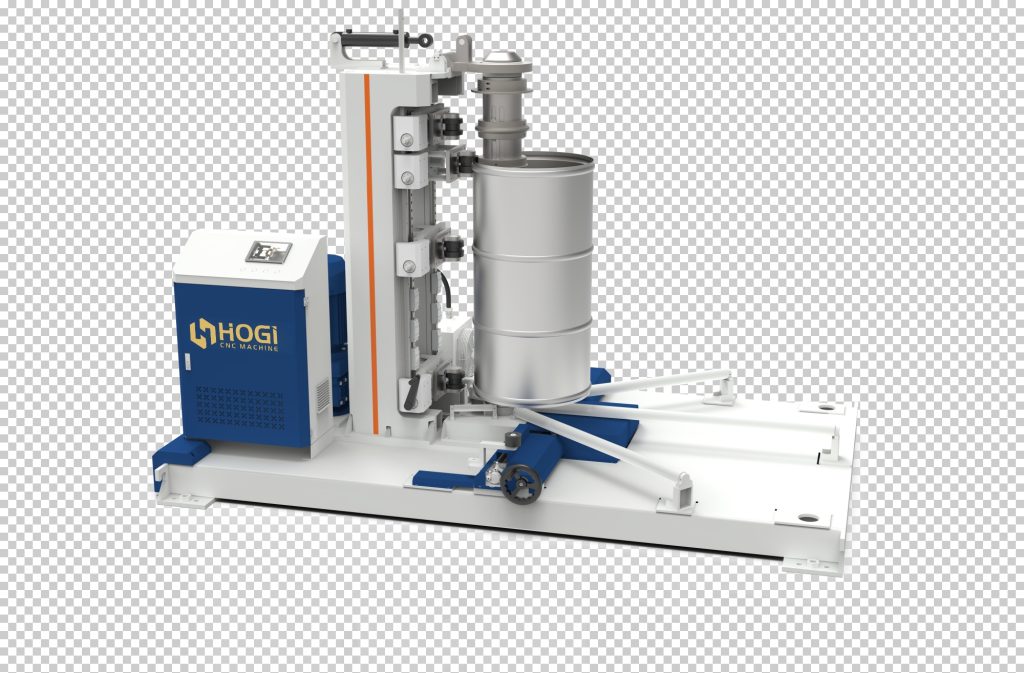
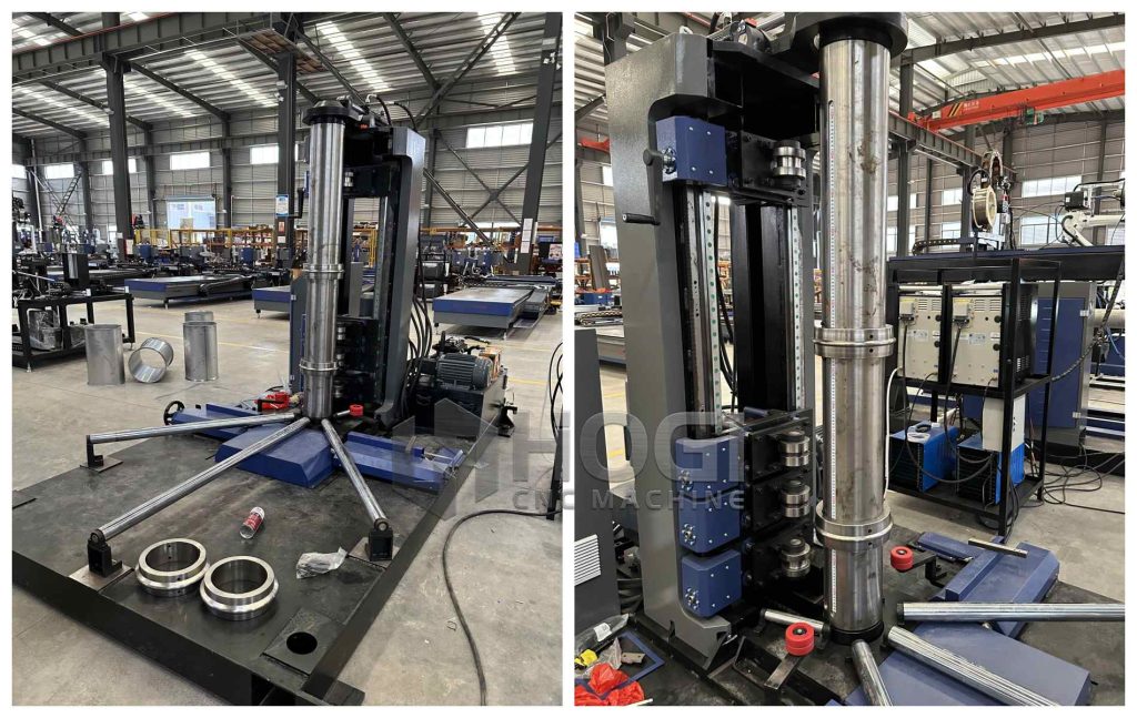
The forming of stiffeners for round ducts (circular ducts) is fundamentally different from that of rectangular ducts. Due to their geometric arched structure, round ducts inherently possess excellent resistance to external pressure and deformation. However, to further enhance the rigidity of large-diameter ducts, reduce wall thickness (to save material), or facilitate alignment during duct butt joints, the **rolling groove (ribbing/corrugation)** process is typically employed.
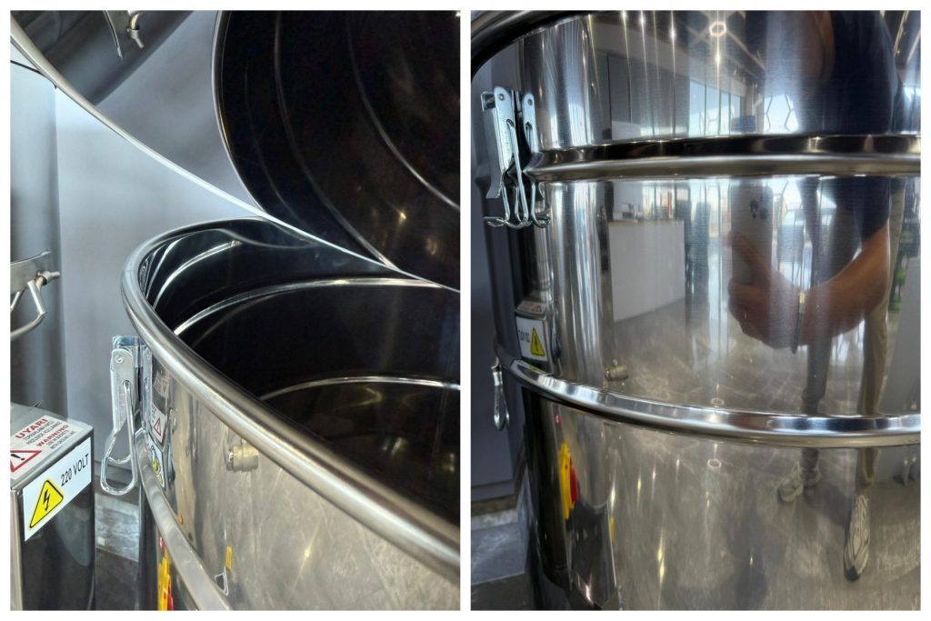
In circular duct manufacturing, these reinforcing ribs are commonly referred to as **“ribs,” “embossed grooves,” or “reinforcing rings”**.
1. Common Forms and Functions of Circular Duct Reinforcing Ribs
Reinforcing ribs for circular ducts are primarily divided into the following two forms, each with its own specific function:
* Single-ring/multi-ring stiffeners (circumferential stiffeners):
* One or more raised (or recessed) rings are rolled along the circumference of the duct.
* Primary function: Significantly enhances the duct’s radial compressive stiffness, preventing collapse under negative pressure or expansion and deformation under positive pressure.
* Reinforcing ribs with positioning function (butt-joint ribs):
* A raised ring is rolled at a certain distance (e.g., 20\text{mm} \sim 50\text{mm}) from the duct end.
* Primary function: Serves as a thrust-stopping and positioning surface when two duct sections are joined via a socket connection, ensuring consistent insertion depth during installation while enhancing the strength of the joint.
2. Core Forming Processes and Equipment
The forming of circular duct ribs primarily depends on the type of duct being manufactured (spiral ducts vs. traditional straight-seam circular ducts):
① In-line Beading for Spiral Ducts
* Process Principle: Spiral ducts are formed by continuously rolling and seaming galvanized steel strip using a spiral duct machine. Modern high-performance spiral duct machines pass the steel strip through a set of beading rollers before it enters the forming head, pressing 1 to 2 continuous shallow beads into the center of the strip in-line.
* Features: As the steel strip is spirally wound, these ribs form spiral-shaped reinforcing ribs on the finished duct. This process requires no secondary processing and is extremely efficient, allowing even extra-large-diameter spiral ducts (such as those with a diameter of \Phi 1000\text{mm} or greater) to be manufactured using relatively thin sheet metal.
② Beading on Straight-Seam Round Ducts (Electric Beading Machine/Rolling Drum)
* Process Principle: For straight-seam round ducts formed by first rolling the tube into a circle and then welding or seaming the edges, the reinforcing ribs are created through secondary processing using a **swaging machine (rotary machine)**.
* The operator places the end of the round tube between the machine’s upper and lower forming rollers.
* When the foot switch is pressed, the rollers clamp down and rotate, driving the round duct through a full rotation and thereby extruding a circular rib onto the duct wall.
* Features: High flexibility; by replacing different rollers (dies), U-shaped, V-shaped, or even flanges for connections can be formed.
Technical Support & Services
🔧Installation & Commissioning
Professional on-site setup and calibration of your flanging punching machine for optimal performance.
📋Operator Training
Hands-on training for CNC programming, punching pattern setup, and routine maintenance procedures.
⚙️Permanent Lubrication Support
Factory-sealed bearings — no maintenance needed. Replacement service available when required.
🔄Custom Mold Design
Design and manufacturing of custom flanging molds and punching dies for specific customer requirements.
🛡️2-Year Warranty
Comprehensive warranty coverage on CNC system, hydraulic components, and structural frame.
HOGI HGFB Heavy-Duty Series — Automatic Flanging & Punching Machine (With Molds)
| Product Processing Range (Diameter) | 300 – 1600 mm |
| Material Thickness | 1–6 mm |
| Material | Stainless Steel / Carbon Steel |
| Total Power | 12.5 KW |
| Power Supply | 380V / 50HZ |
| Programming Forms | Input Specification Dimensions |
| Control System | China CNC Touch Screen System |
| Program Storage | Recipe storage up to 999 sets |
| Repeat Positioning Accuracy | ±0.5 mm |
| Loading & Unloading Method | Manual (single clamping) |

Industrial Fan Blower Flanging Machine — Flanging Process Diagram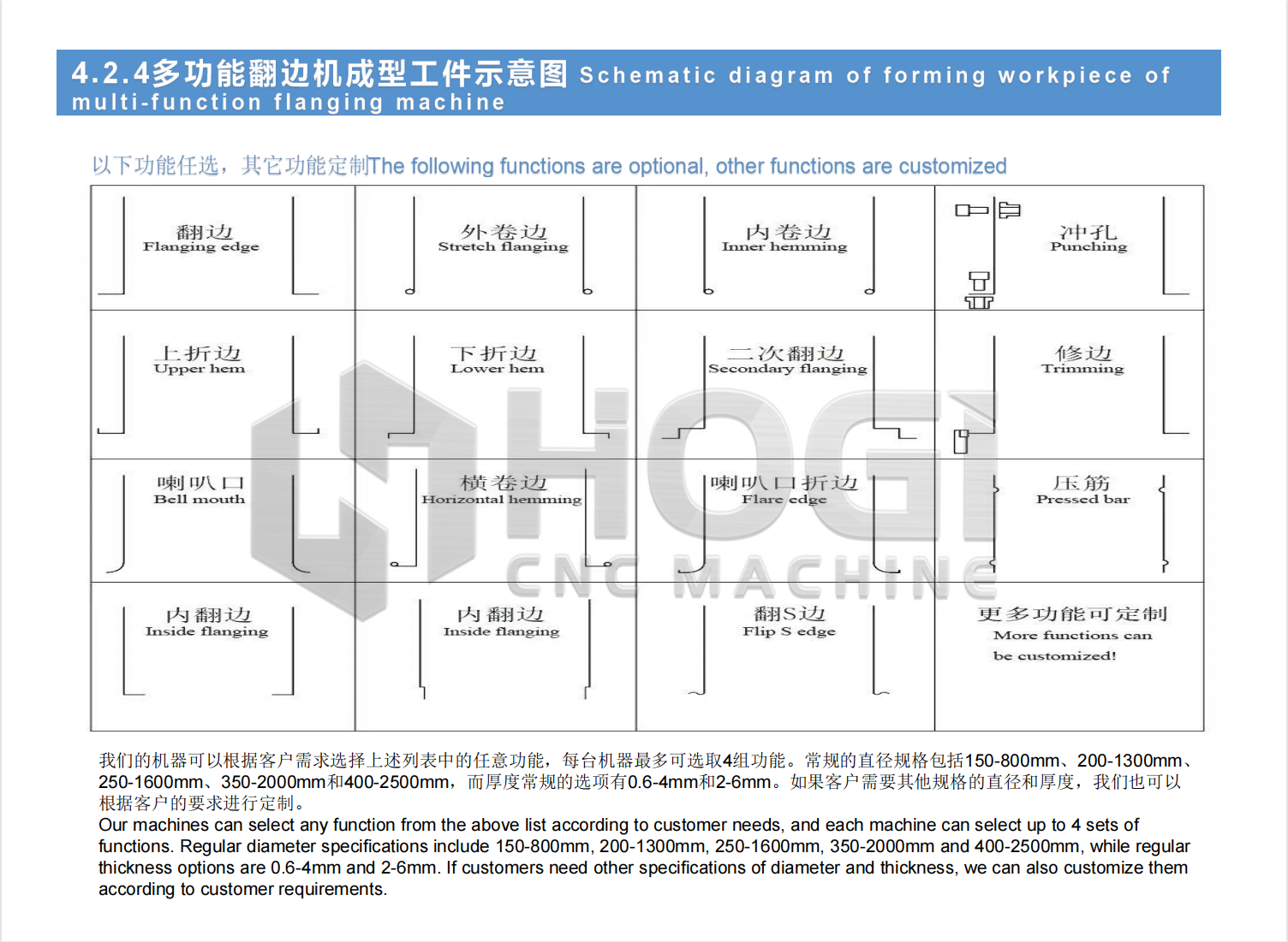
Axial Fan Centrifugal Fan Flanges — Completed Flange Profile
Video
HOGI Automatic Hydraulic Flanging Punching Machine — Live Demonstration
Live Demonstration Highlights
Watch our HOGI automatic hydraulic flanging punching machine in action — available in HGF series (flanging only) and heavy-duty series (flanging + punching with molds). This video showcases CNC drive technology, absolute encoder punching synchronization, and adjustable clamping pressure for industrial fan and ductwork applications.
- CNC Drive Flanging Operation: See the full touch screen CNC control in action — digital control of flanging diameter, thickness, and speed. The machine delivers stable flanging work with superior efficiency and safety compared to older flanging machine types.
- Absolute Encoder Punching Synchronization: Watch the punching system using absolute encoder positioning to synchronize hole locations with ±0.5mm repeat accuracy. Programmable hole count and spacing — round holes or waist slots based on customer requirements.
- Adjustable Clamping Pressure Demonstration: Live demonstration of clamping pressure adjustment via CNC system. Prevents plate slippage on different material thicknesses (1mm to 6mm) — productivity 50-80% higher than old-type flanging machines.
- Wide Processing Range: See the machine processing flanges from 100mm to 1600mm diameter, with flange width from 6mm to 50mm. Applications include axial fans, centrifugal fans, industrial ductwork, and tank cylinders.
Engineered for Industrial Fan, HVAC & Valve Industries
As demonstrated in the video, HOGI flanging punching technology is optimized for industrial fan housings (axial and centrifugal), ventilation ductwork, valve flanges, and tank cylinders. The combination of CNC drive, absolute encoder punching synchronization, permanent lubrication, and adjustable clamping pressure delivers faster production, lower maintenance, and superior flange quality. Processing diameter from 100mm to 1600mm (customizable), thickness from 0.4mm to 6mm, supporting stainless steel, carbon steel, and galvanized sheet. HOGI provides complete installation, operator training, custom mold design, and spare parts support worldwide.