01 Fabrication of Reducing Ducts
Reducing ducts are used to connect ventilation ducts of different cross-sections and at points where the dimensions of the ventilation ducts change. Reducing ducts include rectangular reducing ducts and round-to-square reducing ducts.
1) Fabrication of Rectangular Reducing Ducts
Rectangular reducing ducts are used to connect two rectangular ducts of different diameters. Rectangular reducing ducts come in two types: concentric and eccentric.
The unfolding of concentric rectangular variable-diameter ducts can be performed using the triangular method. Based on the known dimensions of the larger duct side, the smaller duct side, and the height of the variable-diameter duct, create the front view and top view, then unfold using the triangular method. The drawing method is shown in the figure below.
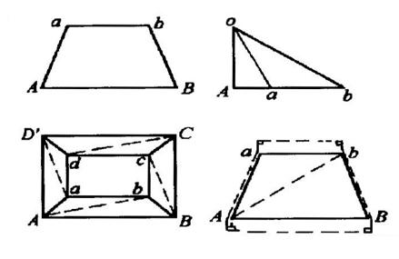
The unfolding method for eccentric rectangular variable diameter pipes is basically the same as that for concentric rectangular variable diameter pipes. The triangular method is still used for unfolding, and the drawing method is shown in the figure below. After unfolding, consider a short straight pipe section similar to that of a circular variable diameter pipe to ensure a tight connection with the flange.
2) Manufacturing of Tianyuan Dangfang Reducing Pipes
Tianyuan Dangfang is used for connecting ventilation ducts to equipment such as ventilators, air conditioners, and air heaters, as well as for connecting sections where the cross-section changes from circular to rectangular. Tianyuan Dangfang comes in two types: concentric and eccentric.
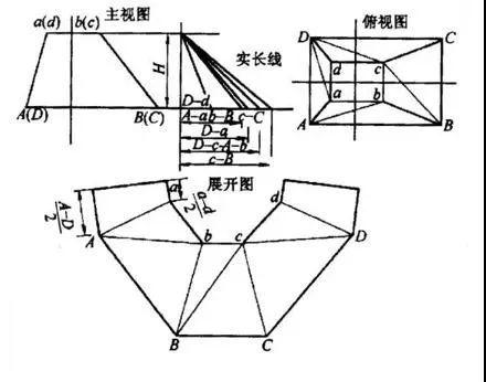
For concentric round-to-square transition pipes, the unfolding can be done using the triangle method or an approximate conical unfolding method. The triangle method is based on the known diameter D of the round pipe, the dimensions A-B and B-C of the rectangular duct sides, and the height h. A front view and top view are drawn, and the upper circular pipe opening is divided into equal parts and numbered. The triangle method is then used to create the unfolding diagram. The drawing method is shown in the figure below.
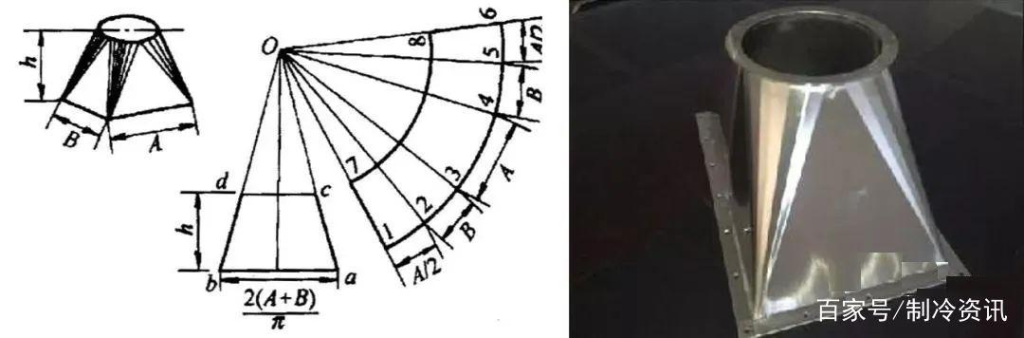
The drawing method using the cone method is shown in the figure below. This method is relatively simple, and the round and square openings are the correct size, but the height is slightly smaller than the specified height. Generally, corrections can be made on the short straight pipe of the extended flange during processing and manufacturing.
02 Fabrication of Air Duct Elbow Deflector Blades
1) For inner and outer rectangular air duct elbows requiring the installation of deflector blades, the following specifications must be followed for fabrication and installation:
Long side length R, inner chord length a;
When R/a ∈ [0.35, 0.5), add 1 deflector blade with spacing from inner to outer being 0.35a, 0.65a;
When R/a ∈ [0.14, 0.35), add 2 guide vanes with spacing from inner to outer being 0.2a, 0.3a, 0.5a;
When R/a ∈ [0.067, 0.14), add 3 deflector plates with spacing from inner to outer being 0.1a, 0.15a, 0.25a, and 0.5a.
2) The deflector plates use the same arc as the inner chord of the duct elbow, with a spacing of 10 cm from each side flange.
3) The deflector plates are made of the same material and thickness as the duct they are installed in, secured with galvanized rivets Φ4;
4) The curvature of the deflector plates aligns with the curvature of the duct elbow they are installed in, ensuring smooth installation without deformation.
5) The ends of the deflector plates are straight and parallel to the duct flanges. The deflector plates are tightly secured to the duct at the riveted joints, with no deformation or warping.
6) Duct elbows should generally use concentric curved pipes with a curvature radius equal to one side length of the plane; when the duct length is ≥500mm, deflector blades must be installed. The deflector blades are made of galvanized sheet metal with a thickness of δ≥0.75mm. The arc length of the guide vanes should match the inner arc length of the bend and form a concentric circle; when the height is greater than or equal to 1250mm, reinforcement measures should be taken.
7) Guide vanes should be manufactured and installed after the bend is completed.
8) Notes: The inner side of the duct bend must not be a right angle; it must be a curved arc.
03 Rectangular Duct T-Joints and Cross-Joints Fabrication
1) For T-joints and cross-joints, the seams at the branching points must be tightly sealed. If any cracks are found, they should be filled with sealant.
2) If the height of the branch duct in a T-joint or cross-joint is less than that of the main duct, the transition diameter should be adjusted based on the on-site layout, either with a bottom-level or top-level transition. The transition section should be fabricated according to the fabrication requirements for duct transition sections.
3) For duct tees and crosses where the side branch length along the main airflow direction is shorter than the main duct, the branch opening should be designed as a diameter transition.
4) The branch pipes connecting to the main duct in duct tees and crosses should generally use concentric arc-shaped bends with a curvature radius equal to one side length of the plane; When the longer side of the duct is ≥500mm, deflector blades must be installed. The construction of deflector blades is detailed in the relevant sections of this manual.
5) Notes: The side branch ducts of three-way or four-way ducts should be connected to the main duct using a lap joint; direct riveting to the main duct is not permitted. Square-to-round transition ducts should not be directly connected to square duct boxes. This would increase local resistance and noise.
04 Fabrication of duct branch pipes
1) Prior to riveting the duct to the flange, conduct a technical quality review. Place the flange over the duct, leaving approximately 6–9 mm of flange overlap at the pipe end. The duct centerline must be perpendicular to the flange plane. Then, use rivets to secure the duct to the flange, leaving flange overlap on all four sides.
2) The flange should be flat and tightly against the flange. The corners of the flange should not be torn. When bending the corners, they should be rounded. When applying adhesive, it should be applied in appropriate amounts and evenly, without any buildup.
3) The direction of the branch duct opening should follow the airflow direction.
05 Internal Flange Duct Fabrication
Internal flange duct fabrication: The requirements for the thickness of galvanized steel sheet, specifications of angle steel flanges, duct seams and flange flanges, and bolt hole spacing for flange connections shall comply with the low-pressure external flange duct fabrication standards specified in the “Code for Acceptance of Construction Quality of Ventilation and Air Conditioning Engineering GB50243.”
06 Fabric Flexible Joint Manufacturing
1) The length of the fabric flexible joint is 150–300 mm. It must be installed in a straight line and cannot be used for misalignment or size changes.
2) Angle steel flanges must be installed at both ends of the fabric flexible joint, with flange specifications matching those of the connected duct flanges.
3) The ends of the canvas flexible joint are connected to the flanges using a folded edge with a width of 8 mm. The canvas surface is secured with L-shaped folded edge galvanized steel strips (δ = 1.2 mm), with the folded edge width of the strip being 8 mm, and the width of the other side matching the width of the angle steel edge.
4) The canvas is connected to the flange using M4 cap screws for easy removal and replacement in case of damage. The screw caps are all on the outer side of the flange, with the inner side nuts exposed by 2 threads. The screw hole spacing from the corners is 10mm, and the intermediate spacing is 8–100mm.
5) The canvas overlap configuration is as shown in the figure below, with an overlap width B = 15 mm, and double hemp thread is used for sewing.
6) During fabrication, first secure the two flanges of the canvas joint using 8 bolts (bolt length determined by the length of the canvas flexible joint, with fixing points at the 4 corners and the center of each side’s bolt holes) through the flange bolt holes. This ensures the canvas remains flat and wrinkle-free during installation.
7) Notes: The canvas for the smoke exhaust system is made of silicone-coated titanium-coated fabric; the canvas for the ventilation and air conditioning system must undergo mold-proof treatment; both ends of the canvas flexible joint must be secured with mounting brackets; when manufacturing the canvas flexible joint, the canvas must be laid flat, wrinkle-free, and without misalignment; the canvas and flange must not be secured using rivets or screws, as this may result in insufficient tightness between the canvas and flange, leading to damage and difficulty in replacement.
8) Mandatory Provision: The material used for flexible short ducts in smoke exhaust systems must be non-combustible. (See Clause 5.2.7 of the “Code for Acceptance of Construction Quality of Ventilation and Air Conditioning Engineering” GB50243 for details.)