


Minimum rolling diameter is one of the most misunderstood figures in cylindrical sheet metal fabrication. A machine specification may list a reference diameter, but that number does not automatically apply to every plate, every thickness, every material grade, or every finished-part tolerance. A cylinder made from 0.8 mm cold-rolled steel behaves very differently from one made from 1.0 mm stainless steel, even when both begin with the same blank width and target diameter.
For production engineers, estimators and fabrication managers, the practical question is not simply “Can this plate be rolled?” A better question is: “Can this material be rolled to the required finished diameter, with acceptable roundness, seam fit-up and repeatability?” The answer depends on the interaction between material properties, roller geometry, plate thickness, pre-bending quality and springback correction. This guide explains how to evaluate those factors before a trial roll, a machine selection decision or a production-line layout is finalized.
Why Minimum Rolling Diameter Is Not One Fixed Number
A published minimum diameter is normally a reference condition, not an unconditional guarantee. It may be based on a particular plate material, yield-strength limit, thickness, rolling width and roller arrangement. If any of those variables changes, the final diameter may change as well.
In practical rolling work, the plate is plastically deformed when it passes through the rollers. After pressure is released, the material attempts to recover part of its original shape. This elastic recovery is known as springback. The rolled shell therefore opens slightly after forming, which can make the actual finished diameter larger than the diameter indicated during the rolling pass.
Minimum diameter must be evaluated as a combined result of machine geometry and workpiece behavior. The upper roller diameter matters, but it is not the only factor. Side roller position, lower roller clamping, plate width, material strength and required tolerance all affect the result.
Machine Geometry Sets the Starting Limit
Every rolling machine has a physical forming limit determined by its roller diameters, center distances and available side-roller travel. A plate cannot be formed to a diameter smaller than the machine geometry can support without excessive local stress, unstable plate tracking or unacceptable marking.
For example, a smaller upper roller generally allows tighter cylinder formation than a larger upper roller when material and thickness are comparable. However, a small roller does not automatically mean that every high-strength material can be rolled to a very small diameter. The machine must still have adequate force, stable clamping and sufficient roller travel for the required plate width and thickness.
Material Properties Change the Forming Result
Yield strength is especially important. A material with a higher yield strength resists permanent deformation more strongly and tends to recover more after roller pressure is removed. This is why two plates with the same thickness can produce different cylinder diameters after using the same rolling program.
Cold-rolled carbon steel, stainless steel, galvanized sheet and aluminum should not be treated as interchangeable inputs. Stainless steel commonly requires more springback compensation than mild steel in similar forming conditions. Aluminum can form readily, but surface marking, material temper and local buckling still require careful process control.
Finished-Part Requirements Determine Whether the Result Is Acceptable
A cylinder for a simple cover or duct sleeve may allow a relatively generous diameter tolerance. A shell that must enter a longitudinal seam welding station, receive a flange, mate with an existing pipe, or form part of a pressure-related assembly often needs a more controlled result.
This means that a cylinder can be technically possible to roll but still unsuitable for the intended process. If the shell opens after rolling, has uneven ends or requires excessive manual correction before welding, the forming method may not meet the real production requirement.
Inputs to Collect Before Evaluating Rolling Capacity
A good rolling assessment begins with complete workpiece data. Missing information causes incorrect assumptions, especially when the requested part has a small diameter, a thin wall or a high-strength material.
Plate Thickness and Rolling Width
Thickness affects the force required to form the plate and influences springback behavior. A thicker plate usually requires more rolling force, while a very thin plate may be more vulnerable to surface marking, slipping, edge waviness or deformation during handling.
Width matters because a wide plate creates a larger contact area and may require different support conditions than a narrow strip. A long cylindrical shell can also sag or lose roundness if it is not supported correctly after rolling. For this reason, the plate width should always be provided together with thickness and target diameter.
- State the nominal plate thickness and permitted thickness variation
- State the developed blank width and finished cylinder length
- Identify whether the blank is rectangular, tapered or pre-cut with special geometry
- Confirm whether protective film or surface-finish requirements affect roller contact
Material Grade and Yield Strength
Material descriptions such as “stainless steel” or “carbon steel” are not sufficiently precise for a close rolling evaluation. Different grades can have different yield strengths, elongation characteristics, surface conditions and work-hardening behavior.
The relevant technical information should include material grade, temper where applicable, specified yield strength, tensile strength and surface condition. If the exact grade is not yet known, use the highest expected yield-strength condition for preliminary planning. This provides a safer estimate than assuming the easiest material in the product range.
Target Diameter and Measurement Basis
Specify whether the target value is an inside diameter, outside diameter, centerline diameter or nominal mating diameter. This avoids a common error: one team designs to inside diameter while another checks the rolled part using outside diameter.
The inspection method should also be defined before trial production. A tape measure around the shell, a diameter tape, a ring gauge, a template and a coordinate inspection method may produce different levels of confidence. For critical work, define both the nominal diameter and the permitted ovality or roundness tolerance.
Required Seam Condition
The seam area is a useful indicator of whether rolling is complete. If the plate edges do not meet evenly, the issue may come from inaccurate pre-bending, inadequate correction passes, poor blank squareness or uneven material behavior.
Before sending a cylinder to a joining station, inspect the seam for gap, height mismatch and edge curvature. A shell that appears round from a distance may still have poor seam fit-up. This is particularly important for components that will be welded longitudinally, where seam alignment influences both weld quality and final distortion.
Understanding Springback in Plate Rolling
Springback occurs because not all deformation remains permanent. During rolling, the plate experiences bending stress through its thickness. Some regions exceed the yield point and deform plastically, while other regions retain elastic strain. When the load is removed, the elastic component attempts to recover, opening the formed radius slightly.
In simple terms, the machine may need to form the plate to a slightly tighter radius than the final required radius. The amount of overbending should not be guessed from one universal formula because it depends on the actual material, roller arrangement, plate thickness, width and production condition.
Why High-Strength Materials Need More Attention
Higher-strength materials generally require greater forming force and often show greater elastic recovery. A process that produces an acceptable result on low-carbon cold plate may leave a larger-than-required finished diameter on a stronger stainless steel sheet.
Work hardening can add another variable. When a material is repeatedly corrected or overworked, its response can change across subsequent passes. The best approach is usually to use controlled correction passes rather than applying an extreme single adjustment that risks marking, local flattening or loss of roundness.
Why Thickness Does Not Explain Everything
It is tempting to assume that thinner material always creates more springback or that thicker material always creates less. In reality, thickness must be evaluated together with material strength and bending radius. A change in material grade can be more important than a small thickness change.
The relationship between radius and thickness is also relevant. A very tight radius relative to plate thickness places greater demand on the forming process. If the requested diameter approaches the practical capability limit, trial rolling becomes essential instead of relying only on theoretical calculations.
Springback Must Be Recorded, Not Rediscovered
For repeat production, each successful part should create a usable process record. The record can include material grade, thickness, blank width, target diameter, roller positions, clamping condition, number of passes and final inspection result.
Over time, this creates a practical database of proven settings. It reduces setup time for recurring work and helps distinguish a material-related change from a machine-alignment issue. It also improves communication between engineering, production and quality teams.
Pre-Bending and Remaining Straight Edge
Even when the main cylinder diameter is correct, poor edge pre-bending can create problems at the leading and trailing ends of the plate. A sheet cannot be bent perfectly to its extreme edge while it is supported between rollers. As a result, some remaining flat edge is normal. The engineering objective is to reduce that flat section enough that the seam closes accurately and the finished shell meets its roundness requirement.
Why Flat Ends Matter
A remaining flat edge can create an open seam, an uneven seam gap or a visible flat area near the weld. In a duct, tank or cylindrical housing, that condition may interfere with fit-up, create an alignment problem for a welding fixture or require manual reforming.
For thin material, excessive correction can introduce dents or surface marks. For thicker material, insufficient pre-bending can leave a pronounced flat end that cannot be corrected easily after the main rolling pass. This is why edge pre-bending should be treated as a distinct operation rather than an incidental part of the cycle.
Checks Before Full Rolling
- Confirm the plate is square to the roller centerline before clamping
- Verify the leading edge is clean and free of burrs that could affect contact
- Pre-bend the first edge and inspect the curvature before advancing the plate
- Pre-bend the trailing edge before the final forming pass
- Check that the two edges will meet with acceptable gap and height alignment
These checks prevent a common mistake: continuing to roll a plate that already has an incorrect edge condition. Once a shell is nearly closed, correcting a poor pre-bend may require repeated passes that consume time and can affect surface quality.
Reference Comparison for Common Rolled Materials
| Material Type | Typical Forming Consideration | Springback Tendency | Key Production Check | Recommended Trial Approach |
|---|---|---|---|---|
| Cold-rolled carbon steel | Generally predictable when grade and thickness are stable | Moderate | Confirm thickness and yield-strength variation between coils or batches | Run a first-piece roll and record final diameter after unloading |
| Stainless steel | Surface protection and springback control are important | Moderate to high | Inspect for marking, seam opening and diameter recovery | Use controlled correction passes and preserve a proven setting record |
| Galvanized sheet | Coating condition and edge quality affect appearance | Depends on substrate grade | Check coating damage and burr-free edges before forming | Test on representative coated material, not uncoated substitute sheet |
| Aluminum sheet | Temper, surface protection and local buckling resistance vary widely | Material dependent | Monitor surface marks and edge distortion | Use a sample from the actual temper and finish condition |
This table is a planning reference rather than a substitute for material data or a trial roll. Actual springback should always be confirmed using the intended material, thickness and finished-part geometry.
A Practical Workflow for Estimating the Finished Diameter
The following workflow helps teams move from an initial drawing to a controlled production decision. It does not replace a formal engineering calculation where regulated or safety-critical equipment is involved, but it provides a disciplined approach for normal cylindrical fabrication planning.
Collect the Complete Part Definition
Start with the developed blank size, material grade, nominal thickness, target diameter, finished cylinder length and seam requirement. Include any flanges, bead rolls, stiffeners or post-forming operations that may change the part after rolling.
Review the Material Against the Machine Range
Compare material thickness, width and yield-strength limit with the planned machine capacity. Do not use only the maximum thickness value from a specification. Capacity depends on the combination of thickness, width, yield strength and target diameter.
Where the part diameter is close to the stated minimum diameter, allow a conservative margin. Small changes in material condition or springback can move the result outside the required tolerance.
Set a First-Pass Forming Target
For a new job, use the target finished diameter to establish an initial roller setting. The first pass should be treated as a controlled trial, not as a final production setting. Measure the unloaded part, inspect seam closure and compare results with the drawing.
Apply Measured Correction
If the cylinder opens too much, adjust the process gradually to form a slightly tighter radius. If the cylinder is too tight, reduce the correction accordingly. Record the direction and amount of change rather than relying on operator memory.
Verify More Than Diameter
A correct diameter does not guarantee a good cylinder. Check roundness, end flatness, seam fit-up, surface condition and axial straightness. These checks are important when the part will move into a welding or assembly process.
Rolling Evaluation Flowchart
Confirm material grade, thickness and width
                ↓
Define target inside or outside diameter
                ↓
Check yield strength against machine capacity
                ↓
Review roller geometry and minimum diameter reference
                ↓
Prepare representative blank and pre-bend both edges
                ↓
Run controlled first-pass roll
                ↓
Measure unloaded diameter, roundness and seam fit-up
                ↓
Apply springback correction with controlled passes
                ↓
Record proven settings for repeat production
Typical Application: Small Stainless Steel Cylinder for a Ventilation Assembly
A fabrication workshop needs to produce a short stainless steel cylinder that will later connect to a ventilation assembly. The part has a relatively small diameter, a visible external surface and a longitudinal seam that must align accurately for joining.
Background: The workshop has previously rolled similar carbon steel parts successfully, but the stainless steel shell opens more after rolling and the seam edges do not meet consistently on the first trial pieces.
Challenge: The team initially attempts to solve the issue by increasing roller pressure in one large adjustment. This improves the diameter on one sample but creates uneven edge condition and makes surface protection more difficult to maintain.
Process Approach: The team confirms the actual material thickness and grade, checks that the blank is square, improves the pre-bend on both edges and uses smaller correction passes. After each pass, the unloaded shell is measured for diameter, roundness and seam alignment.
Result Verification: The selected process setting is accepted only after the shell meets the required diameter range, shows no excessive flat end and provides consistent seam fit-up for the downstream joining operation. The final roller settings and inspection values are stored as a repeat-production reference.
How Machine Selection Relates to Diameter Planning
Machine selection should follow the workpiece data, not the other way around. A useful equipment review considers the smallest target diameter, widest plate, highest expected yield strength and most demanding material within the planned product range. This prevents the common problem of choosing a machine that works for one sample but lacks a stable process window for normal production variation.
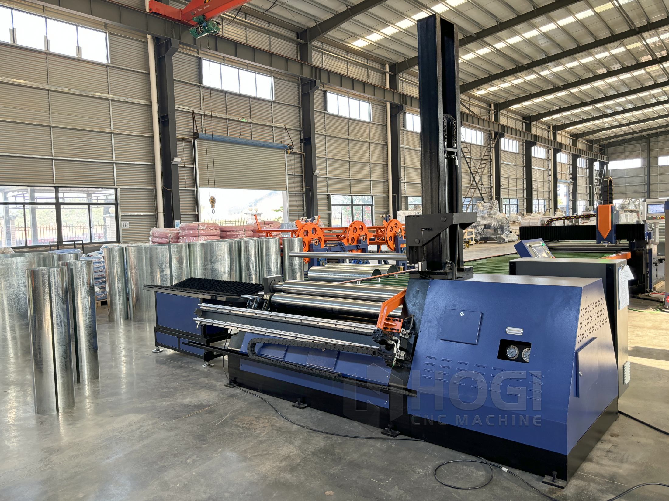
For specifications covering roller sizes, thin-sheet full-servo configurations and hydraulic CNC configurations for heavier plate ranges, review the available 4 roller plate rolling machine configurations against your actual material, thickness, width and diameter requirements.
Diameter planning is also connected to quality troubleshooting. If the finished shell is conical, barrel-shaped, out of round or difficult to close at the seam, the problem may involve more than springback. Roller alignment, clamping, blank loading and edge condition should also be reviewed. Read the plate rolling defects troubleshooting guide here.
When rolled shells move directly into a seam-welding process, final diameter and seam orientation must remain controlled during transfer. See the rolling-to-welding cell design guide here. For tapered workpieces, the part-development method and feed path are different again; see the steel cone rolling guide here.
Frequently Asked Questions
Can one listed minimum rolling diameter apply to every material?
No. A listed minimum diameter is normally tied to a reference material, thickness and yield-strength condition. Stainless steel, higher-strength carbon steel, wider plates or different thicknesses may require a larger practical diameter or additional correction passes.
Does applying more roller pressure always reduce the finished diameter?
Not always in a predictable way. More pressure can tighten the formed radius, but an excessive adjustment can create surface marking, uneven ends, loss of roundness or unstable plate travel. Controlled incremental correction is normally safer than one extreme adjustment.
Why does stainless steel often require more springback correction?
Stainless steel grades often have mechanical properties that produce greater elastic recovery after forming than lower-strength mild steel under similar conditions. The actual result depends on grade, temper, thickness, radius and the rolling process.
What information should be supplied before requesting a rolling capability review?
Provide the material grade, yield strength if available, thickness, blank width, finished cylinder length, target inside or outside diameter, required tolerance, seam condition and expected production quantity. If the workpiece will be welded or flanged afterward, include that information as well.
How many trial pieces are needed for a new rolling job?
The number depends on material consistency, tolerance and product complexity. At minimum, complete one controlled first-piece evaluation using the actual production material. More trials may be needed for tight diameters, visible stainless surfaces, high-strength materials or components that require precise downstream seam alignment.
How do I distinguish springback from a roller-alignment problem?
Springback usually changes the overall diameter after unloading while preserving a generally uniform cylinder shape. An alignment problem is more likely to produce cone shape, barrel shape, inconsistent edge curvature or a seam that closes unevenly from one end to the other.
HOGI Plate Rolling Guidance for Diameter-Sensitive Parts
HOGI develops rolling equipment, intelligent welding equipment and integrated processing lines for HVAC, ventilation, fan, pipeline and cylindrical sheet metal fabrication. The company provides full-servo and hydraulic CNC rolling configurations for different thickness ranges, material types and cylinder-diameter requirements.
For diameter-sensitive projects, the most useful starting point is a complete workpiece review: material grade, thickness, width, target diameter, allowable tolerance, seam requirement and downstream process. This approach helps match the rolling configuration to the actual part rather than relying on a single maximum-thickness or minimum-diameter figure.
Authoritative Sources
Springback | Metalworking: Sheet Forming
https://dl.asminternational.org/handbooks/edited-volume/35/chapter-abstract/466007/Springback
Bending of Sheet Metal | Metalworking
https://dl.asminternational.org/handbooks/edited-volume/35/chapter/461819/Bending-of-Sheet-Metal
Measurement of Springback
https://wpfiles.mines.edu/wp-content/uploads/aspprc/ResearchMaterials/Publications/216-Carden.pdf
Sheet Metal Forming
http://web.mit.edu/2.810/www/files/lectures/lec9-sheet-metal-dcooper-2016.pdf
Temperature-Dependent Material Modeling for Structural Steels
https://nvlpubs.nist.gov/nistpubs/TechnicalNotes/NIST.TN.1907.pdf