


A rolling to welding production line connects plate rolling, workpiece transfer, seam closing, longitudinal welding and inspection into one controlled fabrication workflow. For HVAC ducts, fan housings, stainless steel chimneys, tanks, flues and cylindrical pipe components, this connection determines whether parts move smoothly, whether roundness is preserved and whether the seam arrives at welding in the correct position.
Placing a rolling machine and a seam welder in the same workshop does not automatically create an efficient production line. The space between stations, the way a shell is supported, the direction of transfer, the cycle time of each operation and the quality checks before welding all affect final output. A weak handoff can create queues, force operators to reshape cylinders manually and introduce seam mismatch that should have been prevented upstream.
This guide explains how to plan a rolling to welding production line for cylindrical sheet metal parts. It focuses on factory layout, workpiece movement, cycle balancing, seam orientation, recipe control and inspection points. It is intended for process engineers, production managers and project teams evaluating a new fabrication cell or improving an existing rolling and welding workflow.
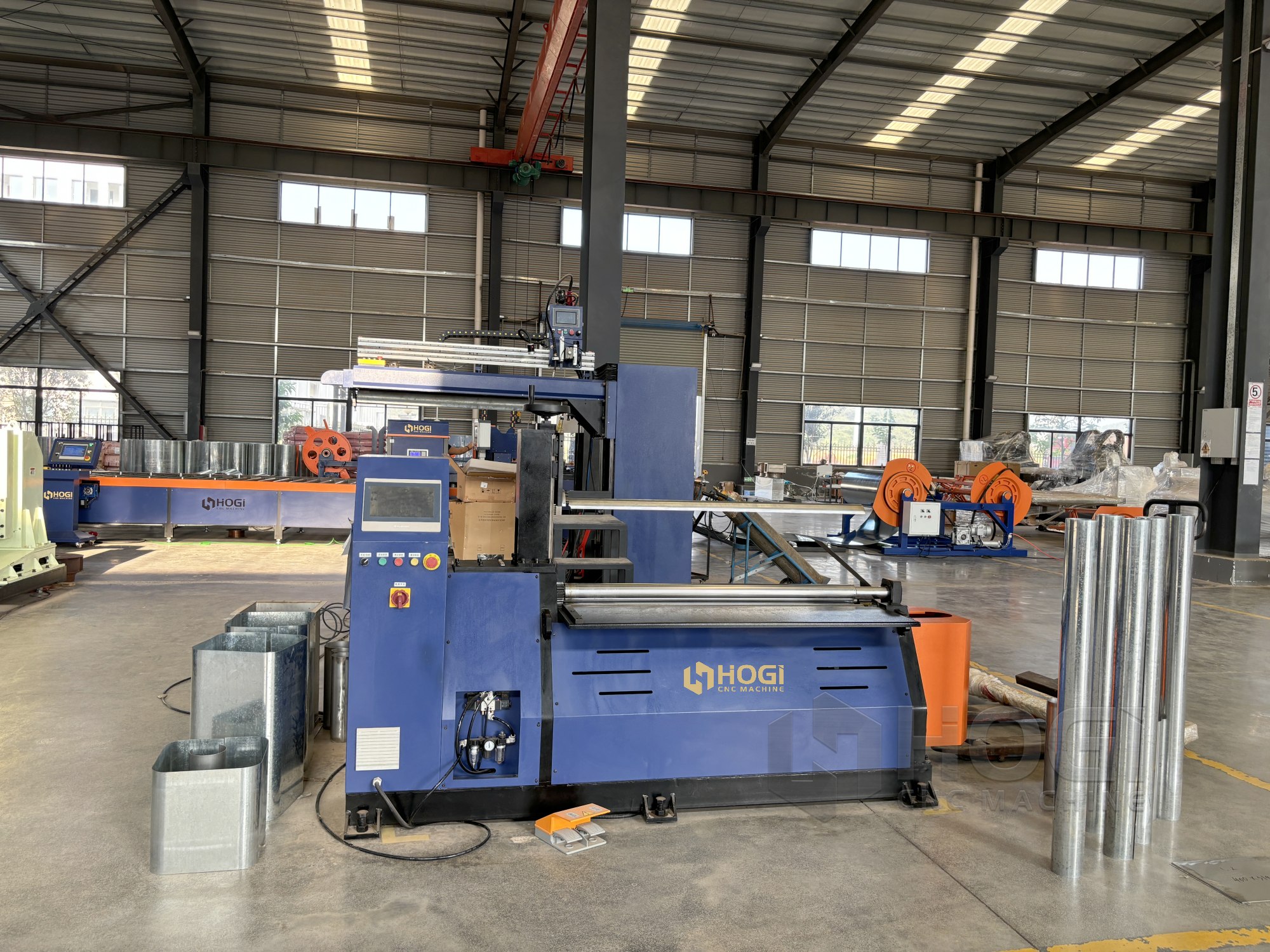
When a Stand-Alone Rolling Machine Is No Longer Enough
A rolling to welding production line becomes practical when the same cylindrical parts are produced repeatedly and manual transfer begins to affect quality, labor time or seam consistency. The objective is not simply to connect machines. It is to ensure that each station delivers a stable workpiece condition to the next station.
A stand-alone rolling machine remains useful for low-volume work, frequent product changes and workshops that produce many different part types. However, a connected process should be considered when rolled shells wait in large queues, operators repeatedly rotate parts to locate seams, or the welding fixture is used to force poor cylinder geometry into place.
Indicators for a Connected Production Cell
- Rolled shells accumulate before seam welding.
- Operators carry or roll cylindrical parts across the workshop floor.
- Thin shells lose roundness during storage or transfer.
- Seam orientation is lost before the shell reaches welding.
- Seam closing requires repeated manual correction.
- Rolling capacity is significantly faster or slower than welding capacity.
- Similar part sizes are produced frequently enough to justify a repeatable workflow.
Automation can be introduced in stages. A basic line may use manual loading, guided roller supports and a welding fixture. A more advanced cell may add powered transfer rollers, seam-position sensors, PLC signals, recipe matching and integrated material handling. The appropriate level depends on product range, production volume, material sensitivity and available floor space.
Define the Workpiece Before Designing the Line
The line should be designed around the workpiece, not around a preferred machine arrangement. A layout that works for a short carbon steel cylinder may not be suitable for a long thin-gauge stainless steel shell. The most demanding product in the intended range should guide the engineering review.
Diameter, Length and Thickness Range
Diameter affects rolling capacity, support-cradle design, transfer clearance and fixture access. Shell length affects how many support points are required. Thickness affects rolling force, springback behavior and the risk of distortion during handling.
Define the smallest and largest cylinder diameters, the minimum and maximum shell lengths, the plate thickness range and the expected material widths. Also identify whether the line must process one family of repeat parts or many different product types. A line built around only one easy workpiece may become inefficient when the product mix changes.
Material and Surface Requirements
Carbon steel, galvanized steel, stainless steel and aluminum require different contact conditions. Stainless steel may need clean, non-marking support surfaces. Galvanized sheet requires attention to edge quality and coating damage. Thin aluminum shells may require wider, softer support contact to reduce local dents.
The selected transfer system should protect the finished surface as well as preserve geometry. A support method suitable for unpainted carbon steel can be unsuitable for visible stainless steel or coated sheet. Roller covers, cradle materials and support spacing should therefore be selected according to the part’s final-use requirement.
Seam Type and Welding Method
Define the joint before planning the rolling-to-welding handoff. A butt seam, lap seam or special edge profile has different fit-up requirements. The rolling station must provide a shell with appropriate edge curvature, stable diameter and accessible seam location.
TIG, MAG and laser welding also have different needs for seam condition and fixture stability. A higher-speed welding process generally requires more consistent part presentation. A TIG process may allow greater visual control but still needs a stable gap, clean surface and predictable seam alignment.
Core Stations in a Rolling to Welding Production Line
A rolling to welding production line should use a clear sequence in which every station has a defined input, output and quality responsibility. This reduces repeated handling and makes it easier to identify the source of a defect when quality changes.
Material Loading and Blank Orientation
The loading station introduces the plate into the line. It may use a manual loading table, guides, vacuum lifting, magnetic handling, powered conveyor or an automatic sheet feeder. Regardless of automation level, the critical requirement is consistent blank orientation.
The plate should enter the rolling process in the same direction for repeat production. If the blank includes protective film, grain direction, a seam allowance, a notch or a product label, the system must preserve that information. A clear loading reference helps prevent skewed rolling and inconsistent seam location.
Plate Rolling and Edge Pre-Bending
The rolling station forms the flat plate into a shell and prepares both edges for seam closure. It must create more than a nominal cylinder diameter. It must also deliver adequate roundness, controlled remaining straight edge and stable seam fit-up.
Within a rolling to welding production line, the rolling station should not pass forming errors downstream. If the shell arrives at welding with a cone shape, flat ends or an unstable seam gap, the welding fixture becomes a correction tool instead of a joining tool.
For a product-focused review of available four-roll plate rolling equipment options, compare the machine range with the actual material, thickness, width, yield strength and required cylinder diameter.
Shell Support and Transfer
After rolling, the shell should move to the next station without being dropped, dragged or left unsupported on the floor. The transfer system can use fixed cradles, adjustable roller supports, powered roller conveyors or guided handling systems.
The support arrangement should maintain roundness while allowing access to the seam. For long shells, multiple supports may be required to avoid sagging. For thin shells, contact surfaces should be broad enough to reduce local denting. For visible stainless steel, clean non-marking supports may be necessary.
Seam Orientation and Seam Closing
The shell should arrive at welding with the seam in a known orientation. If the seam rotates during transfer, operators must locate it again, reposition the shell and verify alignment before welding can begin. This increases cycle time and creates variation.
Seam orientation can be maintained through cradle geometry, guide stops, support rollers, locating tabs, sensors or product-specific fixtures. The correct method depends on the product range and level of automation. For repeated work, even a simple mechanical seam-up reference can save significant setup effort.
Longitudinal Seam Welding
The welding station receives the rolled shell, aligns the longitudinal edges, clamps the part and completes the weld. Stable torch travel, seam accessibility, correct shielding conditions and repeatable part positioning are essential.
The welding fixture should stabilize a correctly formed shell rather than force an incorrectly rolled part into shape. If operators routinely use clamps to pull wide gaps closed or correct large offsets, the process should be reviewed at the rolling and transfer stages.
Inspection and Discharge
Inspection should take place before finished shells are mixed with accepted production. Depending on the application, checks can include diameter, roundness, seam appearance, weld penetration verification, length, flange fit-up or leak testing.
After inspection, the discharge method should protect the cylindrical part from dents and uncontrolled rolling. The finished part should remain identifiable for the next assembly, packaging or storage operation.
Balance Cycle Time Across the Line
Cycle balance is one of the most important planning tasks in a rolling to welding production line. The output of the complete line is controlled by its slowest repeated operation. If rolling takes 45 seconds but seam welding, unloading and inspection take 90 seconds, increasing rolling speed alone will create a larger queue of unfinished shells.
Measure the actual process time at each station, including loading, alignment, pre-bending, rolling, transfer, seam closing, welding, inspection and discharge. Machine movement time is only one part of the total cycle. Operator intervention, waiting time, program change and quality checks must also be included.
Identify the True Constraint
The longest consistent station time is normally the first place to investigate. In cylindrical fabrication, the bottleneck may be welding, manual seam alignment, material transfer or inspection rather than rolling itself.
Once the constraint is identified, improvements may include reduced setup time, improved seam fit-up, better transfer supports, a controlled buffer or parallel capacity. Improving a station that is not the bottleneck may have little effect on total line output.
Use Buffers to Absorb Variation
A buffer between rolling and welding can allow one station to continue during short interruptions at the other. However, buffers should be controlled. Large uncontrolled queues create handling risk, product mixing and loss of seam orientation.
Useful buffers use individual cradles, guided roller lanes, labeled locations or simple part tracking. The buffer capacity should reflect actual cycle variation, expected downtime and available floor space rather than a general rule.
Plan for Product Mix and Changeover
A line that produces one diameter all day has different needs from a line that produces many part sizes in small batches. For mixed production, define changeover tasks for roller settings, support positions, welding fixtures, transfer guides and program recipes.
If frequent changeovers become the main loss of productive time, it may be more effective to create dedicated paths for high-volume parts while retaining a flexible cell for low-volume work.
Workpiece Transfer Is a Quality-Critical Process
Workpiece transfer is a quality-critical stage in a rolling to welding production line. A shell can leave the rolling machine within tolerance and become oval, dented or seam-misaligned during manual movement. Transfer design should be treated as part of the forming and welding process, not only as a logistics task.
Select Support Points Carefully
Support points should be chosen based on shell diameter, length, wall thickness and weight. Long shells may require several support locations. Small-diameter shells may need side guides to prevent uncontrolled rotation. Large shells may require adjustable cradles that support the cylinder without blocking seam access.
Where parts are transferred after welding, consider temperature and seam position. Support materials should remain suitable for the expected part condition and should not damage the finished surface.
Prevent Uncontrolled Rotation
Cylinders naturally roll if placed on an unrestricted surface. This can create safety risks, lose seam orientation and damage the part. Use chocks, cradles, roller stops or controlled conveyors to keep shells stable during movement and waiting periods.
Clear aisles and sufficient handling space are equally important. The workpiece path should be reviewed with the actual part diameter and the actual handling method, not only with a layout drawing.
Use Basic Control Signals and Recipe Matching
A connected line works more reliably when each station knows whether a part is ready, present, safe to transfer or complete. This does not require a complex factory software system for every project. A PLC-based cell can use practical signals to reduce uncertainty and improve fault finding.
Useful Station-to-Station Signals
- Ready for loading
- Correct material or blank present
- Rolling cycle complete
- Part safe to transfer
- Transfer position available
- Welding station ready
- Seam position confirmed
- Welding complete
- Inspection accepted or rejected
These signals make line stoppages easier to diagnose. They also help prevent a part from moving before the next station is ready or before it has been inspected for the correct condition.
Match Rolling and Welding Recipes
A product recipe can include material type, thickness, blank width, target diameter, rolling program, seam type, welding speed and inspection requirement. Matching these settings reduces the risk of rolling one part with the correct program and welding it with parameters intended for another part.
This is especially important when the same cell processes multiple diameters, different material types or varied joint designs. Recipe control does not remove the need for operator inspection, but it provides a repeatable reference for production.
Quality Checkpoints Before and After Welding
| Station | Input Condition | Expected Output | Key Inspection Point | Typical Bottleneck |
|---|---|---|---|---|
| Loading | Correct blank and material identification | Square, correctly oriented plate | Thickness, material and blank alignment | Manual loading delay |
| Rolling | Correct roller and clamping setup | Round shell with controlled edge curvature | Diameter, roundness and flat-end condition | Repeated correction passes |
| Transfer | Stable rolled shell | Preserved shape and seam orientation | Surface marks, ovality and seam position | Manual rotation or unsupported shells |
| Seam Closing | Correctly formed shell | Stable seam fit-up | Gap, edge mismatch and seam straightness | Fixture correction of poor shells |
| Welding | Stable joint and correct recipe | Consistent longitudinal seam | Weld appearance and distortion | Slow cycle or frequent intervention |
| Inspection | Completed cylinder | Accepted or segregated workpiece | Final diameter, roundness and seam condition | Delayed feedback to upstream stations |
Inspect the shell after rolling, before it enters welding. This is the best point to identify cone shape, barrel shape, flat ends, plate slippage and seam mismatch. If the shell is already outside tolerance at this stage, changing welding parameters will not resolve the root cause.
For corrective methods related to cone shape, barrel shape, flat ends and tracking drift, read the plate rolling defects troubleshooting guide.
Rolling to Welding Production Line Planning Flow
Define product range and final quality requirements
                ↓
Confirm material, thickness, diameter, length and seam type
                ↓
Set the process boundary from loading through discharge
                ↓
Calculate real rolling, transfer and welding cycle times
                ↓
Define seam orientation and workpiece support method
                ↓
Plan controlled buffer positions between stations
                ↓
Set control signals and match rolling and welding recipes
                ↓
Inspect first-piece geometry before welding
                ↓
Validate final weld quality and update the line layout
Typical Application: HVAC Cylinder and Fan Housing Production
A fabrication operation plans a rolling to welding production line for cylindrical HVAC components in multiple diameters. The existing process uses a stand-alone rolling machine, floor storage and a separate seam welding station. Although both machines can process the parts, operators spend significant time moving shells, locating the seam and reshaping parts that lose roundness during handling.
Background: The production range includes thin galvanized duct shells and thicker fan housing sections. Some parts move directly from rolling to welding, while others wait for a later shift. This mixed workflow makes seam orientation difficult to maintain and creates uneven queues before welding.
Challenge: The rolling station produces some shells faster than the welding station can receive them. The uncontrolled floor buffer allows thin shells to rotate, become mixed with other product sizes and occasionally lose roundness. Operators then spend additional time correcting fit-up at the welding fixture.
Process Approach: The planned workflow uses a defined loading direction, controlled rolling, individual support cradles, a limited buffer, seam-up transfer references and a seam-closing position before welding. Diameter and seam fit-up are checked immediately after rolling, while final weld and dimensional checks take place after joining.
Result Verification: The line design is evaluated by tracking workpiece travel, station cycle time, seam orientation, roundness before welding and the number of parts requiring manual fit-up correction. The layout is accepted only when these conditions remain stable across the intended product range.
How Line Design Connects to Rolling Capability
Line design begins with actual forming capability. If a cylinder opens after rolling because of material springback, the welding station must accommodate the actual formed geometry, not only the theoretical drawing diameter. If the rolling process creates inconsistent diameter or poor edge curvature, adding transfer automation will not solve the root cause.
For guidance on material grade, plate thickness, yield strength, roller geometry and springback, read the minimum rolling diameter and springback guide.
For conical transitions and tapered shells, the blank development, forming path and transfer method differ from a standard cylindrical workflow. Read the steel cone rolling guide before applying a normal cylinder process to cone-shaped workpieces.
Frequently Asked Questions
Should rolling and welding have the same cycle time?
Not exactly, but their actual cycle times should be balanced closely enough that one station does not remain idle or create an uncontrolled queue. A small controlled buffer can absorb normal variation between the two operations.
How much buffer capacity is needed between rolling and welding?
The correct buffer size depends on cycle-time variation, shell dimensions, product mix, available floor space and handling method. It should preserve workpiece condition and seam orientation rather than simply store as many shells as possible.
Can one rolling station feed multiple welding stations?
Yes. This can be effective when seam welding is the constraint and the rolling station has sufficient capacity. The routing method, product identification and fixture compatibility should be clearly defined before implementation.
How is seam orientation maintained during transfer?
Seam orientation can be maintained with cradles, guide stops, seam-up supports, locating tabs, sensors or recipe-based positioning. The best method depends on the degree of product variation and the required automation level.
What information is needed before designing a rolling to welding production line?
Confirm material type, thickness, blank width, cylinder diameter, shell length, seam type, welding process, production quantity, product variation, handling limits, surface requirements and available floor space.
Can one line process ducts, fan housings and tank shells?
It can if the rolling machine, supports, transfer system, seam-closing fixtures and welding parameters cover the complete workpiece range. The line should be reviewed against the most demanding part, not only the most common part.
HOGI Rolling to Welding Production Line Solutions
HOGI develops customized rolling equipment, intelligent welding equipment and rolling to welding production line solutions for HVAC, ventilation, fan, pipeline and cylindrical sheet metal fabrication. A connected system should be planned around workpiece flow, material range, seam requirements, quality checkpoints and realistic production rhythm.
For projects combining rolling, transfer and longitudinal seam welding, HOGI can evaluate part geometry, equipment sequence, handling direction, control requirements and downstream operations. This supports a process in which rolling and welding work toward the same target for cylinder diameter, seam fit-up and production continuity.
Client Testimonial
Note for publication: Add a verified client quotation only after receiving written approval. A suitable quotation should identify the application, such as HVAC duct shells, fan housings or cylindrical tank components, and describe a specific improvement in handling, seam orientation, workpiece flow or setup consistency. Do not publish unsupported claims about output, labor reduction, energy savings or defect-rate improvement.
Authoritative Sources
Materials Handling and Storage
https://www.osha.gov/sites/default/files/publications/osha2236.pdf
Systems Integration for Manufacturing Applications
https://tsapps.nist.gov/publication/get_pdf.cfm?pub_id=821138
A Reference Activity Model for Smart Factory Design and Analysis
https://tsapps.nist.gov/publication/get_pdf.cfm?pub_id=918224
Manufacturing Systems III: Lean Game
https://ocw.mit.edu/courses/2-008-design-and-manufacturing-ii-spring-2025/mit2_008_s25_lec18.pdf