


Plate Rolling Defects: Troubleshooting Ovality, Taper and Seam Mismatch
A rolled cylinder can have the correct average diameter and still fail inspection. Its cross-section may be oval, one end may be larger than the other, or the longitudinal edges may not align for welding. These problems require different checks—not the same machine adjustment.
When troubleshooting a CNC 4 roller rolling machine, first identify the defect and establish when it appears: during rolling, after unloading, during transfer, or after welding. This helps separate forming problems from handling and fit-up problems before changing an approved CNC program.
This guide focuses on practical diagnosis for cylindrical parts. For equipment configurations and production-line options, visit the HOGI CNC 4 roller rolling machine product page.
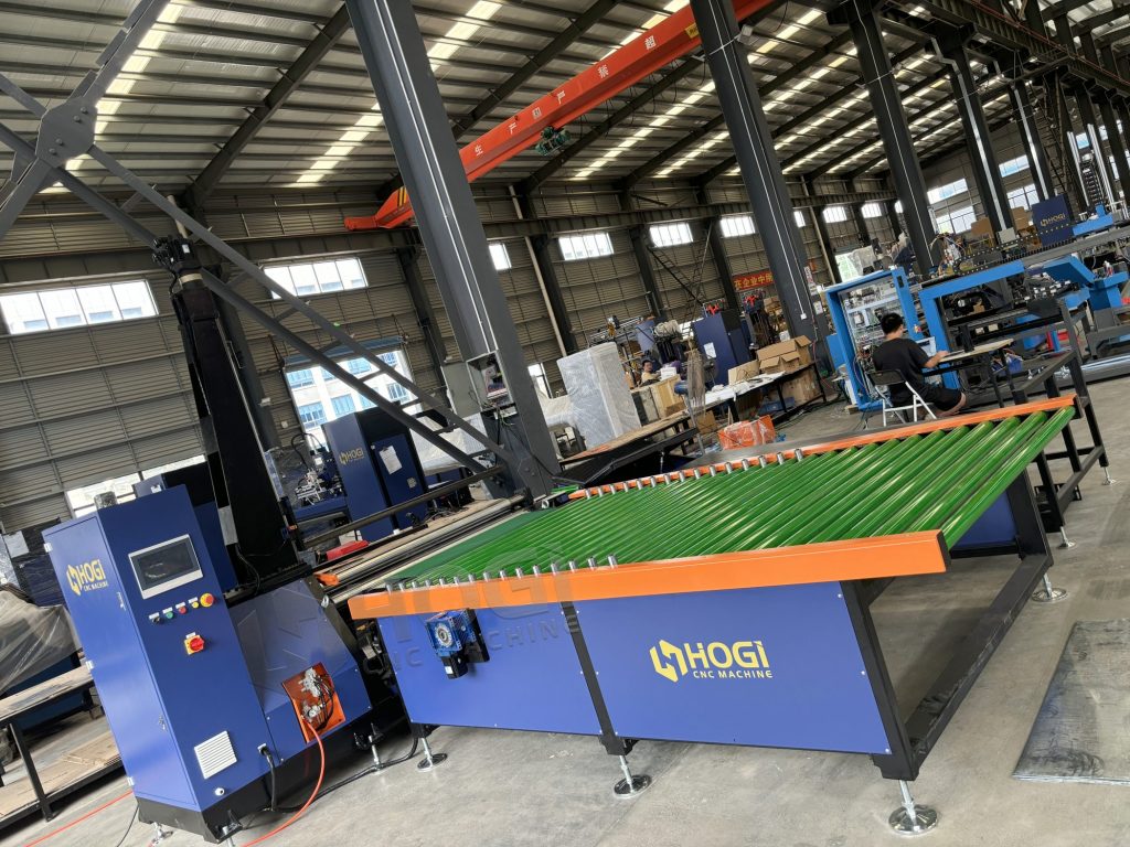
Identify the Defect Before Changing the Rolling Program
Ovality, Taper and Seam Mismatch Are Different Problems
“The cylinder is not round” is not a sufficient diagnosis. Record the specific shape deviation, where it occurs, and whether it is repeatable.
| Defect | What You Observe | What to Check First |
|---|---|---|
| Ovality | Different diameters around the same cross-section. | Measurement direction, support conditions, and whether the shape changes after unloading. |
| Taper | One end of an intended straight cylinder is larger than the other. | Blank squareness, feed alignment, and approved roller-position records. |
| Barrel or hourglass shape | The middle diameter differs from the diameters at both ends. | Measurements along the cylinder length and the machine’s suitability for the forming load. |
| Seam gap variation | The opening between the longitudinal edges changes along the seam. | Blank geometry, taper, end forming, and fit-up conditions. |
| Edge mismatch | The two seam edges do not sit at the same level or their ends do not align. | Whether the mismatch is radial or axial, and whether it appears before or after transfer. |
| Flat ends near the seam | Local straight sections remain beside the longitudinal opening. | The approved leading- and trailing-edge pre-bending process. |
A barrel-shaped shell is not the same as a tapered shell. Similarly, an excessive seam opening is not automatically evidence that the entire cylinder has the wrong diameter. Identify the geometry before choosing a corrective action.
Record Material, Blank Dimensions and Program Revision
Before making changes, create a traceable record of the affected part:
-
- Part drawing and revision.
-
- Material grade, batch identification, and measured thickness.
-
- Blank dimensions and the direction used for rolling.
-
- Target diameter, cylinder length, and applicable tolerances.
-
- CNC program name, revision, and approved setup.
-
- Workpiece support and unloading arrangement.
-
- Photographs showing the defect and measurement positions.
Compare these records with the last accepted batch. A material change, blank revision, or different support arrangement may explain the problem without indicating a machine fault.
Inspect the Cylinder Before Welding
Measure and document the shell before welding wherever the agreed process allows. Once the seam is welded, forming deviations and welding distortion become harder to separate.
Use consistent inspection stages: after rolling, after unloading, after transfer, and after welding. A defect that first appears at a later stage should be investigated at that stage before the rolling program is changed.
How to Measure and Document Cylinder Defects
Measure Diameter at Multiple Positions
For a practical inspection map, identify three axial positions: End A, the middle, and End B. At each position, record diameter measurements in multiple defined directions using a method suitable for the part’s size, stiffness, and required tolerance.
Keep the measurement orientation and support arrangement consistent. Thin or flexible shells can change shape under their own weight, so unsupported and supported measurements should not be compared as if the conditions were identical.
| Inspection Position | Measurements to Record | Diagnostic Purpose |
|---|---|---|
| End A | Diameters in defined directions and local seam condition. | Establish the shape at the first end. |
| Middle | Diameters using the same orientation and support conditions. | Identify possible barrel, hourglass, or local shape variation. |
| End B | Diameters and seam condition using the same method as End A. | Compare the ends for unwanted taper. |
| Longitudinal seam | Gap, radial edge offset, and axial end mismatch at defined points. | Evaluate closure and welding fit-up. |
The difference between maximum and minimum measured diameter at one section is a useful screening value for ovality. However, the drawing or agreed inspection standard must define the acceptance method and limit. A few diameter readings do not replace a full roundness assessment when one is required.
Compare Both Ends and the Middle
Measurements along the length help distinguish different defects:
-
- Different end diameters suggest unwanted taper.
-
- A larger middle diameter than both ends suggests a barrel-shaped profile.
-
- A smaller middle diameter than both ends suggests an hourglass-shaped profile.
-
- Different diameters around one section indicate ovality or another cross-sectional deviation.
More than one defect can be present. Record each separately rather than reducing the inspection result to a single average diameter.
Record Seam Gap and Edge Offset Separately
Seam gap describes the opening between the longitudinal edges. Radial edge offset describes the difference in height between those edges. Axial mismatch describes the difference in their end positions.
These conditions may affect welding fit-up differently. Use the approved joint requirements to determine acceptance; do not assume the welding fixture should force every rolled shell into alignment.
Troubleshooting Ovality After Rolling
Check Whether Ovality Appears Before or After Unloading
If the part is already oval before unloading, investigate the forming setup, end curvature, material variation, and recorded roller positions. Any inspection near the machine must follow the approved stopped-machine procedure.
If the shape changes mainly after unloading, check how the shell is supported. The machine may have been holding a flexible shell in a shape that changes when that support is removed.
Do not alter the CNC program solely because an unsupported shell looks different from one held on the machine. First repeat the measurement under a defined inspection condition.
Review Workpiece Support and Handling
Inspect the unloading and transfer arrangement for changes in support or concentrated contact. Useful questions include:
-
- Is the shell supported at the intended positions?
-
- Does it sag, tilt, or deform during transfer?
-
- Are handling contact points producing local deformation?
-
- Does the measurement result change when the shell orientation changes?
-
- Are operators using the same approved handling method for each part?
For large or flexible cylinders, support equipment is part of the production process—not simply an unloading accessory. Use an engineered handling arrangement appropriate to the workpiece.
Compare Results Across Material Batches
If ovality appears after a material change, compare the actual thickness, grade, blank condition, and available material documentation. A stored program is an approved starting point for defined conditions, not a guarantee of identical results across all material batches.
For a separate discussion of forming limits, refer to minimum rolling diameter and springback considerations. This troubleshooting guide does not replace a material-specific forming assessment.
Troubleshooting Taper Along the Cylinder
Check Blank Squareness and Feed Alignment
When a parallel-sided cylinder develops unwanted taper, check the blank and entry alignment before assuming there is a hydraulic fault.
Confirm that the blank matches the drawing, its reference edges are suitable for alignment, and it enters the rolls according to the approved setup. A skewed entry or unsuitable blank geometry can contribute to uneven forming along the cylinder.
Check whether the same pattern appears on multiple parts. Consistent taper across a batch may point to a repeated setup condition, while an isolated result may relate to a particular blank or handling event.
Review Roller Parallelism and Position Records
Compare the recorded positions with the approved cylindrical-rolling setup. If the machine provides position feedback at both ends of a controlled roll, review those readings and any relevant alarms.
Suspected roller misalignment, inconsistent movement, or position-feedback errors require manufacturer-approved inspection. Do not attempt to correct taper by guessing hydraulic pressures or changing service parameters.
Mechanical alignment, sensor calibration, and hydraulic balancing should be checked by qualified personnel using the machine’s service procedure.
Separate Intentional Cone Rolling from Unwanted Taper
Some equipment supports cone rolling through a dedicated setup or operating mode. Before investigating unwanted taper, verify that the selected program and configuration are intended for a straight cylinder.
Check program names, revisions, and setup records rather than relying only on the operator’s recollection. An incorrect recipe is a different problem from a machine alignment fault.
Troubleshooting Seam Gap and Edge Mismatch
Verify the Developed Blank Dimensions
Check the blank dimensions against the approved development calculation and drawing. The development must reflect the specified diameter reference, material thickness, joint design, and process allowances.
An incorrect blank length can create an excessive opening or unwanted overlap. However, a gap that varies along the seam also requires checks for taper, blank squareness, and local end curvature.
Do not compensate for a blank-development error by repeatedly changing the rolling program.
Review End Forming and Closure Conditions
Local flat sections beside the seam may indicate that the end-forming process needs review. Compare the leading and trailing edges and inspect whether their curvature matches the rest of the shell.
Review the approved pre-bending sequence with the machine supplier when necessary. Any correction must remain within the equipment’s capability and operating procedure.
A fixture may align an acceptable shell for welding, but it should not conceal a forming defect that violates the agreed requirements.
Check Transfer and Welding Fixture Alignment
If seam alignment is acceptable after rolling but changes at the welding station, inspect transfer supports, workpiece orientation, locating references, and the clamping sequence.
Compare the shell in three conditions: supported for inspection, positioned in the fixture before clamping, and held under the approved clamping arrangement. Record when the mismatch first appears.
For welding-equipment selection rather than forming diagnosis, see the longitudinal seam welding machine selection guide.
A Controlled Troubleshooting Workflow
Follow the Defect Through the Process
Identify the defect → Confirm the drawing and measurement method → Inspect after rolling → Inspect after unloading → Inspect after transfer → Compare after welding → Investigate the first stage where the deviation appears.
This sequence helps prevent a downstream handling or welding issue from being treated as a rolling-machine problem.
Change One Approved Process Variable at a Time
Once the likely cause has been narrowed down, use a controlled trial:
-
- Save the original approved program and setup record.
-
- Document the defect and baseline measurements.
-
- Choose one process change permitted by the operating procedure.
-
- Produce a trial part under the same documented conditions.
-
- Measure the result using the same inspection method.
-
- Approve, reject, or escalate the change based on the evidence.
Changing several settings together may produce a better part without revealing why. It also makes the result harder to reproduce on the next batch.
Stop and Escalate Suspected Machine Faults
Stop production and follow the site and manufacturer procedures if there are abnormal movements, unexpected roller-position differences, hydraulic leaks, damaged components, unusual noise, or unreliable safety functions.
Do not bypass interlocks, inspect between moving rolls, or make unapproved pressure and calibration changes. Isolate equipment under the applicable lockout procedure before maintenance or intrusive inspection.
Illustrative Diagnosis Example: Uneven Seam Gap
The following example is hypothetical. It demonstrates a diagnosis method and is not a HOGI customer case or performance claim.
Initial Inspection
A workshop produces straight cylindrical duct sections. Several shells show a wider longitudinal opening near End B than End A.
The operator initially suspects that the target diameter in the CNC program is incorrect. Instead of changing it immediately, the team records the seam gap and cylinder diameters at both ends and the middle.
| Check | Illustrative Observation | Next Step |
|---|---|---|
| Approved program | The program revision matches the previous accepted batch. | Preserve it while checking other changed conditions. |
| Blank inspection | The incoming blanks require further squareness verification. | Check them against the drawing and cutting records. |
| End diameter comparison | End B is larger than End A. | Investigate unwanted taper rather than a uniform diameter error. |
| Process stage | The deviation is present before transfer to welding. | Focus first on blank preparation and rolling setup. |
| Controlled trial | A verified blank is processed with documented entry alignment. | Compare results before authorizing any program change. |
What the Example Demonstrates
A varying seam gap can be a symptom of another geometry problem. Measuring the ends separately and checking the blank can narrow the investigation more effectively than changing the target diameter without evidence.
If the result remains unacceptable, the records provide a useful basis for supplier support and further controlled testing.
Build a Useful Inspection and Support Record
A clear troubleshooting report should allow another person to reproduce the inspection and understand what changed.
-
- Identify the machine, part, material batch, and program revision.
-
- Mark measurement locations on a drawing or photograph.
-
- State whether measurements were taken before or after unloading, transfer, and welding.
-
- Describe the support and fixture conditions.
-
- Record trial changes and the resulting measurements.
-
- Attach relevant alarm records and observations without altering service settings.
For recurring setup issues, use a documented changeover process and first-piece approval rather than relying on memory. A previously successful program should be checked against the conditions of the next job before batch production begins.
Frequently Asked Questions
Why Does a Cylinder Look Round on the Machine but Oval After Unloading?
The support conditions change when the shell leaves the machine. A flexible cylinder may deform under its own weight or during handling. Compare measurements under defined support conditions before deciding whether the cause is forming, unloading, or inspection method.
Should Seam Mismatch Be Corrected Before Welding?
Seam fit-up must meet the approved joint requirements before welding. Determine whether the mismatch comes from blank geometry, rolling, handling, or fixture setup. Do not assume welding or excessive clamping will correct a shell that is outside the agreed forming limits.
Can One CNC Program Be Used for Different Material Batches?
An approved program can be a starting point when the specified material and geometry remain the same. However, actual thickness and material behavior can vary. Use the required first-piece inspection and record any approved recipe changes.
Does Unwanted Taper Always Mean the Rolls Are Misaligned?
No. Blank geometry, feed alignment, an incorrect program, and other setup conditions should also be checked. If those checks do not explain the result, arrange a manufacturer-approved inspection of roller alignment and position control.
Can Average Diameter Confirm That the Cylinder Is Acceptable?
Not by itself. An acceptable average can conceal ovality, taper, or local shape deviations. Inspect the characteristics specified by the drawing and use the agreed measurement method.
What Information Should Be Sent to the Machine Supplier?
Send the machine identification, part drawing, material and thickness, blank dimensions, program revision, measurement map, photographs, and the stage where the defect first appears. Include relevant alarms and trial records so support can investigate the issue without guessing.
Next Steps: From Defect Diagnosis to Stable Production
Reliable troubleshooting starts with a repeatable inspection method. Identify the geometry, locate the first process stage where it changes, and test only approved corrections under controlled conditions.
If you are evaluating equipment for cylindrical ducts, fan housings, or related rolling and welding applications, review the HOGI CNC 4 roller rolling machine configurations. Provide representative drawings, material data, inspection requirements, and handling needs so the proposed system can be assessed against your actual parts.
For technical consultation, contact adaxu@hogimachine.com.