


Plate Rolling and Welding Acceptance Tests: What to Verify Before Production
A successful demonstration does not necessarily prove that a rolling and welding system is ready for your production requirements. One cylinder may look satisfactory while repeatability, transfer conditions, weld quality or sustained output remain unverified.
A plate rolling machine acceptance test should connect the agreed equipment configuration to measurable results on representative parts. Define the material, drawings, inspection methods and production conditions before the trial begins—not after a result is disputed.
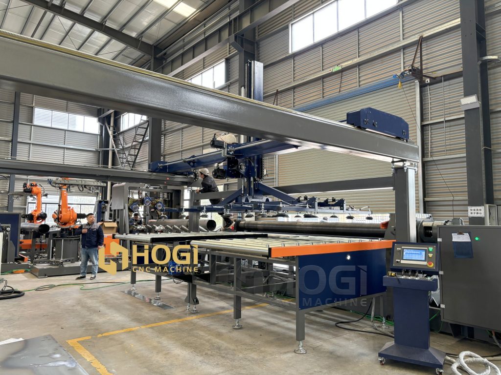
This guide provides a practical framework for testing cylindrical ducts, fan housings and related rolled shells. For specific equipment configurations, visit the HOGI CNC 4 roller rolling machine and integrated rolling-welding equipment page.
Define Acceptance Criteria Before the Trial
Separate Machine Capability from Finished-Part Requirements
Machine positioning, rolled-cylinder geometry and finished welded-part quality are different acceptance subjects. A positioning specification alone does not establish the diameter, roundness or weld quality of every workpiece.
Similarly, successfully rolling a shell does not prove that unloading, transfer and welding will preserve its geometry.
Define which results the project must demonstrate: forming capability, integrated-line performance, finished-part quality or a combination of these.
Agree on Materials, Drawings and Measurement Methods
The test protocol should identify the reference documents and explain how each requirement will be measured.
- Part drawings and approved revisions.
- Material grade, condition and thickness.
- Blank dimensions and preparation requirements.
- Diameter reference: internal, external or another defined basis.
- Dimensional and weld acceptance requirements.
- Inspection positions, equipment and support conditions.
- Test quantity, duration and operating conditions.
Do not apply a website parameter as a universal acceptance limit for every part. Use the limits and methods agreed in the drawing, contract and applicable specifications.
Record the Configuration Being Tested
Identify the machine, controller, program revision, handling equipment, welding process and fixtures included in the trial.
If the demonstrated arrangement differs from the proposed delivery configuration, document the difference and determine which results require verification on the final system.
A trial using a separate handling device or welding fixture should not silently be treated as proof of the complete contracted line.
Choose Representative Trial Parts
Include Normal Production Parts
Select parts that reflect the work the system will perform regularly. Include the relevant material, thickness, diameter, length and joint requirements.
A convenient demonstration sample may show basic operation but provide limited evidence for the intended production mix.
Include Challenging Geometry Within the Agreed Scope
Where relevant, include parts that challenge handling, seam fit-up or dimensional consistency. Examples may include longer shells, flexible thin-wall cylinders or a demanding product-family transition.
Keep all tests within the agreed machine capability and approved operating procedure. Acceptance testing is not an invitation to overload equipment or improvise unsafe trials.
Define the Coverage of Each Sample
| Trial Part Type | Purpose | Conditions to Record |
|---|---|---|
| Typical production part | Verify the normal forming and welding process. | Material, geometry, program and inspection results. |
| Handling-sensitive part | Evaluate unloading, support and transfer. | Support locations, orientation and measurements before and after handling. |
| Different approved product family | Check the scope of mixed-product operation. | Required setup changes and first-piece approval. |
| Repeated part sequence | Evaluate consistency and sustained output. | Consecutive part results, stops, adjustments and good-part count. |
The trial plan should explain what each sample verifies and which requirements remain outside its scope.
Inspect the Rolled Cylinder Before Welding
Check Diameter and Roundness
Measure the shell at defined axial positions and orientations. Record the support condition so measurements can be repeated and compared.
Thin or flexible shells may change shape depending on how they are supported. Comparing an unsupported shell with one held in a fixture can produce misleading conclusions.
Follow the agreed roundness method. A small number of diameter readings can help screen a problem, but may not satisfy a specified full-profile inspection requirement.
Check Length, Taper and End Alignment
Compare the geometry at both ends and the middle where required. This helps distinguish unwanted taper from barrel-shaped or hourglass-shaped deviations.
Record cylinder length and end alignment against the drawing. Use the same references for every trial part.
If a deviation appears, consult our plate rolling defects troubleshooting guide before changing several process settings at once.
Record Seam Gap and Edge Offset
Document the longitudinal opening, radial edge offset and axial end mismatch separately. These describe different fit-up conditions.
Check them against the approved joint requirements before welding. Do not assume that fixture force or welding will correct a shell outside the agreed forming limits.
| Characteristic | Before Welding | After Welding | Acceptance Reference |
|---|---|---|---|
| Diameter and shape | Record at defined positions and support conditions. | Repeat under the agreed final inspection conditions. | Drawing and inspection plan. |
| Length and end alignment | Establish the formed-shell baseline. | Check the finished-part result. | Drawing and specified measurement method. |
| Seam gap | Measure before welding under the agreed fit-up conditions. | Not applicable as an open gap after seam closure. | Joint design and welding requirements. |
| Edge mismatch | Record fit-up before welding. | Inspect the finished joint where required. | Applicable weld and dimensional requirements. |
| Surface condition | Record handling marks or existing damage. | Check for additional damage and required finish. | Customer surface specification. |
Verify Transfer and Welding Fit-Up
Inspect Support During Unloading and Handling
Observe the approved unloading and transfer sequence. Check whether the shell remains adequately supported and reaches the welding station without unacceptable deformation or surface damage.
Compare measurements before and after handling when the test scope requires it. This helps identify whether a deviation begins during forming or downstream movement.
Check Fixture Access and Seam Position
Confirm that the part can be located, clamped, welded and released using the supplied arrangement.
Review access for the welding head and required inspection. Record whether additional manual repositioning or correction is needed beyond the agreed operating method.
Clamping should follow the approved sequence. Do not use excessive force to conceal unacceptable incoming fit-up.
Confirm the Welding Process Included in the Test
Identify the actual welding process, consumables, shielding arrangements and applicable procedure. Avoid treating different process configurations as interchangeable.
If a trial uses one welding method while the contract specifies another, document the difference and agree how the contracted method will be validated.
For process and equipment selection, refer to the longitudinal seam welding machine selection guide.
Inspect the Finished Part After Welding
Compare Pre-Weld and Post-Weld Dimensions
Measure the finished part using the agreed method and inspection condition. Record differences from the pre-weld baseline.
Comparing both stages helps distinguish forming deviations from changes introduced during fit-up, welding or subsequent handling.
Where temperature or restraint can affect the result, the inspection plan should define the measurement condition, including any required cooling and fixture release.
Apply the Agreed Weld Inspection Requirements
Use qualified personnel where required and inspect against the applicable procedure, drawing, code or specification.
Do not accept a weld solely because it looks smooth. The test plan should identify the required characteristics, methods, coverage and acceptance criteria.
Separate Visual Inspection from Additional Testing
Visual inspection can assess accessible surface conditions and joint appearance. It does not establish the absence of internal defects.
Where the application requires additional nondestructive or destructive testing, specify the method and acceptance basis before the trial. The appropriate choice depends on material, thickness, joint geometry, service conditions and applicable requirements.
A production demonstration does not replace pressure-vessel qualification, leak testing or other application-specific requirements when those apply.
Test Repeatability and Production Performance
Run an Agreed Sequence of Consecutive Parts
One acceptable cylinder demonstrates one acceptable result under the recorded conditions. It does not establish sustained consistency.
Agree on the number of consecutive parts or the test duration based on the project requirements. Record every part in the sequence, including rejected or reworked pieces.
If a program or setup is adjusted during the run, document the change. The protocol should state whether the sequence must restart or whether an additional verification run is required.
Record Good-Part Output and Operator Involvement
Define what counts as a good finished part and where it is counted. A shell leaving the rolling station is not automatically an accepted welded cylinder.
Record the operators and manual tasks needed to achieve the result. A production claim should not omit assistance that was essential during the test.
For timing boundaries and overlapping operations, read our rolling and welding line cycle-time guide.
Document Stops, Adjustments and Changeovers
| Production Record | What to Capture |
|---|---|
| Test boundaries | Start and finish times, startup treatment and included operations. |
| Part count | Total produced, accepted, rejected and reworked quantities. |
| Stops | Duration, reason and corrective action. |
| Adjustments | Parameter or setup changes, authorization and affected parts. |
| Operator involvement | Staffing and manual handling, alignment or correction tasks. |
| Changeovers | Previous and next products, preparation and approval times. |
| Configuration | Program revision, fixtures, transfer resources and welding setup. |
For mixed-size production, use the HVAC duct rolling changeover checklist to define setup transitions and first-piece release.
Structure Factory and Site Acceptance Tests
Define the Factory Acceptance Test Scope
A factory acceptance test, or FAT, is performed at the supplier’s facility before shipment under an agreed protocol.
Depending on the contract, it can cover equipment identification, supplied components, functional operation, controls, safety-function verification, representative parts and production performance.
If the complete site arrangement cannot be reproduced, record which interfaces or performance requirements remain to be verified after installation.
Define the Site Acceptance Test Scope
A site acceptance test, or SAT, verifies the installed system under the agreed site conditions.
The scope may include utilities, installation, integration with other equipment, transfer paths, operating resources and relevant performance checks.
Passing FAT does not automatically confirm that every site interface is correct. Equally, SAT does not necessarily repeat every factory test; the agreed protocol should define the required coverage.
| Subject | Factory Test Focus | Site Test Focus |
|---|---|---|
| Equipment configuration | Verify supplied scope against the agreed documents. | Confirm delivered and installed configuration. |
| Controls and functions | Test the available factory arrangement. | Verify installed interfaces and site integration. |
| Representative parts | Demonstrate agreed forming and welding requirements. | Confirm required results under the installed conditions. |
| Handling and layout | Evaluate the demonstrated handling configuration. | Check actual access, transfer and support arrangements. |
| Safety verification | Complete the factory checks within the agreed scope. | Verify installation and integration-dependent requirements. |
| Documentation | Review required manuals, records and supplied documents. | Complete site records, training and final document updates. |
Safety checks must be planned and performed by appropriately qualified personnel using approved procedures. Do not create hazardous conditions or bypass safeguards for a demonstration.
Resolve Open Issues Before Final Sign-Off
Record deviations with a responsible person, required action and verification method. Distinguish issues that prevent acceptance from items that can be closed under an explicitly agreed arrangement.
Any conditional acceptance should document its limits, outstanding obligations and completion dates. It should not silently convert failed requirements into accepted performance.
Build a Clear Acceptance Report
Use an Acceptance Matrix
Connect each requirement to evidence. The following structure can be adapted to the project.
| Test Item | Reference | Method | Acceptance Basis | Result |
|---|---|---|---|---|
| Rolled-cylinder dimensions | Approved part drawing. | Agreed measurement positions and support conditions. | Specified limits. | Measured values and pass/fail record. |
| Seam fit-up | Joint requirements. | Gap and mismatch checks before welding. | Approved fit-up limits. | Values, photographs and disposition. |
| Finished weld | Applicable welding and inspection requirements. | Specified inspection methods. | Applicable acceptance criteria. | Inspection report. |
| Handling and transfer | Approved system layout and operating sequence. | Observed operation and required dimensional comparisons. | Agreed handling and quality requirements. | Observations and deviation record. |
| Repeatability | Approved trial protocol. | Consecutive-part measurements. | Agreed sample and consistency requirements. | Complete part-by-part record. |
| Production output | Contracted performance conditions. | Timed run with defined boundaries. | Agreed good-part output. | Counts, times, stops and staffing. |
Attach Traceable Evidence
Include program versions, material records, measurement sheets, photographs and timing logs. Identify inspection equipment and its required calibration status.
Record the date, equipment identification, test personnel and approvals. Preserve failed results alongside corrective actions and retest evidence.
Use a Documented Closure Process
Acceptance workflow: Agree requirements → Select representative parts → Confirm configuration → Run tests → Record results → Resolve deviations → Complete required retests → Approve the defined acceptance scope.
Final approval should state what has been accepted and identify any remaining obligations. Keep the signed report available for installation, training and future process review.
Illustrative Example: A Sample Passes but the Test Remains Incomplete
The following scenario is hypothetical and is not a HOGI customer case.
A supplier demonstrates one cylinder that meets the agreed rolled dimensions. The buyer is satisfied with its appearance, but the protocol also requires transfer verification, post-weld measurements and a consecutive-part production run.
| Evidence Available | What It Demonstrates | What Still Needs Verification |
|---|---|---|
| One acceptable rolled shell. | The recorded trial produced an acceptable forming result. | Consistency across the agreed sequence. |
| Successful transfer to the fixture. | The demonstrated shell could be transferred. | Required geometry checks after handling and other representative sizes. |
| A visually satisfactory weld. | Observed surface appearance under the inspection conditions. | Other specified weld tests and final dimensions. |
| A recorded machine cycle. | The timed operation completed under those conditions. | Sustained good-part output under the agreed timing boundaries. |
The appropriate response is not to reject useful evidence, but to avoid extending it beyond what it proves. Complete the remaining tests and record the final disposition against the original requirements.
Frequently Asked Questions
Is One Successful Sample Enough for Acceptance?
Only if it satisfies the agreed test scope. A single sample does not automatically demonstrate repeatability, mixed-product capability or sustained line output. Define the required evidence before testing.
Should Dimensions Be Checked Before and After Welding?
When the acceptance plan requires both formed-shell and finished-part results, check both stages. This helps identify whether changes occur during rolling, handling, fit-up or welding.
How Should Cycle Time Be Measured?
State the start and finish events and included operations. Distinguish station cycle time, total part lead time and the interval between accepted finished parts. Record staffing, stops and adjustments during the test.
What If Trial Material Differs from Production Material?
Document the difference and determine which results remain applicable. A trial on a different grade, thickness or condition should not automatically validate the intended production material. Agree on any additional testing.
Does a Smooth Weld Prove That the Joint Is Acceptable?
No. Appearance is only part of the inspection evidence. Apply the required methods and acceptance criteria for the intended application; visual inspection cannot establish the absence of internal defects.
Does Passing FAT Remove the Need for SAT?
Not automatically. Site installation, utilities and integration can introduce conditions not verified at the factory. The contract and approved test plan should define whether SAT is required and what it covers.
Who Sets the Acceptance Tolerances?
The relevant drawings, specifications, applicable requirements and contract establish the acceptance basis. The buyer and supplier should agree on measurement methods and test conditions before the trial.
Next Steps: Verify the System Against Your Actual Parts
A useful acceptance test turns a demonstration into traceable evidence. Agree on requirements, inspect representative parts, document all results and close deviations through controlled retesting.
For forming deviations, read our plate rolling defects troubleshooting guide. For output verification, use the rolling-welding line cycle-time and bottleneck guide. For mixed-product trials, refer to the HVAC duct rolling changeover checklist.
If you are evaluating a CNC 4 roller rolling machine or an integrated cylinder production line, review the HOGI rolling and welding equipment configurations. Send representative drawings, material data, output targets and acceptance requirements to adaxu@hogimachine.com for technical consultation.