


Rolling and Welding Line Cycle Time: How to Find Bottlenecks and Balance Output
A faster rolling machine does not automatically mean a faster cylinder production line. If unloading, seam alignment, welding or inspection cannot keep pace, the next rolled shell simply joins a queue.
To evaluate rolling welding production line cycle time, measure the complete process—not just the time spent forming the cylinder. Distinguish the time required for one part to pass through the line from the interval between consecutive finished parts.
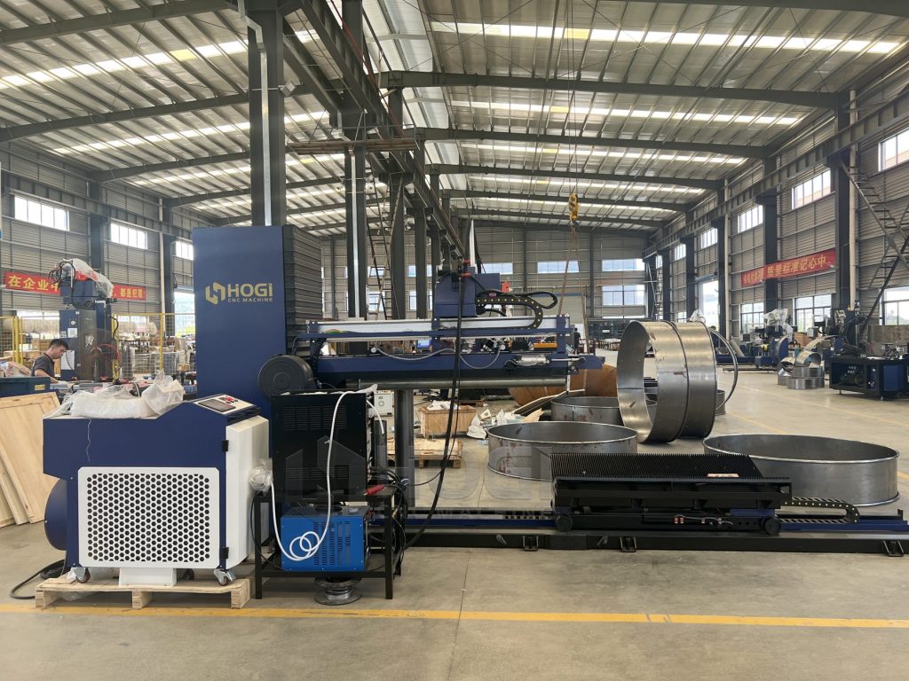
This guide explains how to map station times, identify bottlenecks and estimate practical output for ducts, fan housings and cylindrical shells. For specific equipment configurations, visit the HOGI CNC 4 roller rolling machine and integrated rolling-welding equipment page.
Define the Output Target Before Designing the Line
Start with Required Good Parts per Shift
Begin with the number of acceptable finished parts the workshop needs to deliver. A target based only on rolled shells may overlook welding rejects, inspection holds and rework.
Define the output point clearly. For example, does the target refer to cylinders leaving the rolling station, welded cylinders leaving the fixture, or inspected parts ready for the next production process?
- Required good parts per shift.
- Product dimensions, material grades and thicknesses.
- Inspection and weld acceptance requirements.
- Number of operators and their assigned tasks.
- Planned shift time and scheduled breaks.
The output target should use the same finished-part definition throughout the quotation, trial and acceptance process.
Account for Product Mix and Batch Size
A line producing one repeated cylinder size is different from a workshop alternating between several diameters, lengths and material thicknesses.
Different parts may require different rolling sequences, handling arrangements, welding settings and inspection methods. Measure representative product families rather than assuming that one sample represents the entire production mix.
For high-mix production, also review our plate rolling machine changeover checklist for HVAC ducts. Changeover time must be included consistently in the production plan.
Establish Available Production Time
Record the shift duration and identify time that is excluded from planned production, such as scheduled breaks when the line is not intended to operate.
Then define how setup, maintenance, adjustments and unplanned stops will be recorded. Do not subtract a time loss from the production window and then count the same loss again in an availability factor.
Required production pace: Planned production time ÷ Required good parts.
This gives a demand-based target interval. It does not prove that the equipment can achieve that interval, especially after operating and quality losses are included.
Map the Complete Rolling and Welding Workflow
Material Preparation, Leveling and Cutting
Identify how material reaches the rolling station. Depending on the project, the line may receive prepared blanks or include material feeding, leveling and cutting.
For each stage, record processing time, material positioning, loading and any waiting for the next operation. If blanks are prepared elsewhere, that process may sit outside the immediate line boundary but can still limit material availability.
Rolling, Unloading and Transfer
The CNC 4 roller rolling machine is one station in a wider production system. Its forming time must be considered together with loading, positioning, unloading and transfer.
Record whether the rolling machine can begin the next part while the previous shell is being transferred. This depends on the actual equipment arrangement, handling resources and approved control sequence.
A shared operator, lifting device or transfer platform can prevent overlap even when individual machines are capable of operating independently.
Seam Alignment, Welding and Inspection
Welding station time includes more than arc-on or laser-on time. Locating the shell, aligning the seam, clamping, welding, releasing and unloading can all occupy the station.
Also identify inspection activities that prevent the station from accepting the next part. If inspection occurs in a separate area, record its capacity and the transfer requirements.
Typical process map: Material preparation → Leveling and cutting, if included → Rolling → Unloading and transfer → Seam alignment and clamping → Welding → Release and inspection.
Adapt this map to the actual project. Not every line includes every stage, and some operations may be combined or performed outside the line.
Distinguish Station Cycle Time from Total Lead Time
Processing Time Is Only Part of Station Occupancy
For line balancing, measure how long a station remains occupied by one part before it can accept the next. This can include loading, positioning, processing, release and unloading.
| Time Category | What It Covers | Why It Matters |
|---|---|---|
| Processing time | Rolling, cutting, welding or another transformation. | Shows the time spent performing the main operation. |
| Loading and positioning | Placing and locating the blank or shell. | May prevent the station from beginning its process. |
| Release and unloading | Opening fixtures and removing the completed part. | May keep the station occupied after processing ends. |
| Transfer time | Movement between production stages. | Can constrain output if transfer resources are shared or too slow. |
| Waiting time | Waiting for material, an operator or downstream space. | Reveals starvation, blocking or resource conflicts. |
| Changeover time | Switching between approved product setups. | Affects batch and shift output, especially in mixed-size production. |
Sequential Operations Versus Overlapping Operations
In a fully sequential process, one part may pass through every stage before the next part begins. Under that arrangement, the output interval can approach the sum of the required operation times.
In a coordinated line, different stations may process different parts at the same time. The total time for one part to travel through the line is then different from the interval between completed parts.
Under ideal steady-state conditions, independent stations with adequate transfer capacity may approach an output interval set by the slowest station. Startup, shared resources, synchronization, buffers and stoppages can make actual output slower.
Why Adding All Station Times Can Misrepresent Output
Adding all operation times can describe a no-wait processing path for one part. It does not necessarily describe steady-state line output when operations overlap.
Conversely, using only the fastest machine’s cycle time overstates line capacity if another station or shared resource limits the flow.
Every production claim should state whether it represents a station cycle, a finished-part output interval or total part lead time.
Find the Actual Bottleneck
Compare Complete Station Times
Time several representative cycles using the same measurement boundaries. Record typical variation instead of relying only on the best cycle observed during a demonstration.
Compare complete station occupancy times and identify the stage that consistently constrains finished-part output. Then check whether it is limited by processing, handling, adjustments or waiting.
Record Blocking and Starvation
A station is blocked when it cannot release a part because the next stage or buffer is unavailable. It is starved when it is ready to work but has no incoming part.
- Frequent blocking after rolling suggests a downstream or transfer limitation.
- Frequent welding starvation suggests insufficient incoming flow or unreliable transfer.
- Queues at inspection may indicate that completed parts cannot be released quickly enough.
- Repeated waiting for one operator may indicate a shared-labor constraint.
These patterns provide evidence for investigation; they do not replace measured timing and resource analysis.
Check Whether the Bottleneck Changes with Product Size
The limiting station can change between product families. A longer cylinder may occupy welding for more time, while a large or flexible shell may require more careful handling.
Use a product-family timing matrix to identify these differences. A layout optimized for one part should not automatically be treated as suitable for every diameter, length and thickness.
Balance Rolling and Welding Capacity
Match Transfer Capacity to Station Output
Transfer equipment must move and position parts at the required pace without damaging the shell or obstructing another station.
Review the transfer route, positioning time, support arrangement and return movement. Include any time when the same device must serve more than one operation.
If cylinders become oval or develop seam mismatch during transfer, address the quality issue before increasing speed. See our plate rolling defects troubleshooting guide for checks that distinguish forming defects from unloading and handling problems.
Plan Buffers for a Defined Purpose
A buffer can help absorb short interruptions between stations. However, it does not increase the sustained capacity of a slower station.
Specify what the buffer is intended to cover: a short interruption, a transfer delay or temporary variation in processing time. Then consider available space, workpiece support, identification and safe access.
A preliminary buffer estimate can use the interruption duration divided by the target output interval. Treat this only as a starting point; the final design must account for product sizes, variability and the actual control logic.
Consider Parallel Stations Only When the Data Supports Them
A second welding station may help if welding consistently limits output and upstream operations can supply enough acceptable shells.
Before adding capacity, check whether the real constraint is welding itself, clamping, transfer, inspection or operator availability. Parallel equipment still needs compatible controls, handling resources and a safe operating arrangement.
For a separate discussion of welding equipment and process options, read the longitudinal seam welding machine selection guide.
Illustrative Line-Balancing Example
The following values are hypothetical and demonstrate the calculation method. They are not HOGI equipment specifications or a production guarantee.
Compare Sequential and Overlapping Production
| Stage | Illustrative Time per Part | Assumption |
|---|---|---|
| Blank preparation | 40 seconds | Complete station cycle within the example boundary. |
| Rolling | 60 seconds | Includes the assigned loading and unloading tasks. |
| Transfer | 20 seconds | Dedicated transfer resource with no conflicting tasks. |
| Fit-up and welding | 100 seconds | Includes alignment, clamping, welding and release. |
| Inspection | 30 seconds | Independent inspection station. |
If the stages are fully sequential with no overlap, the example totals 250 seconds per part. The idealized output is 3,600 ÷ 250 = 14.4 parts per hour.
If the stages can operate independently on different parts, with adequate transfer and buffering, the 100-second fit-up and welding station sets the idealized steady-state limit. That corresponds to 3,600 ÷ 100 = 36 parts per hour before losses.
| Arrangement | Idealized Output Interval | Idealized Output per Hour |
|---|---|---|
| Fully sequential, no overlap | 250 seconds | 14.4 parts |
| Independent, overlapping stages | 100 seconds | 36 parts |
The overlapping example assumes that staffing, controls, transfer and support arrangements genuinely permit simultaneous operation. It excludes startup, interruptions and rejects.
A Faster Rolling Station May Not Increase Output
In this example, reducing rolling from 60 to 45 seconds does not change the idealized 100-second line interval because fit-up and welding still limit output.
The improvement may create useful reserve capacity, but it should not be reported as a proportional increase in finished-cylinder output.
A Bottleneck Improvement Can Reveal the Next Constraint
If the complete fit-up and welding station cycle is reduced to 75 seconds without compromising quality or safety, it remains the slowest stage in this example. The revised idealized rate becomes 3,600 ÷ 75 = 48 parts per hour.
After any change, remeasure the line. Transfer capacity, labor or another stage may become the next constraint.
Calculate Practical Good-Part Output per Shift
Choose a Consistent Calculation Method
Two approaches are useful, but they should not be mixed without checking what each already includes.
- Measured-output approach: use good parts produced during a representative timed run.
- Planning approach: start with an ideal line interval and apply documented operating-loss assumptions.
If measured output already includes stops, slow cycles and rejects, do not apply those same losses again.
Include Availability, Performance and Quality Losses
For a planning calculation, define the three factors consistently:
- Availability: the share of planned production time during which the line runs.
- Performance: the operating rate compared with the defined ideal rate.
- Quality: the share of produced parts that meet the agreed good-part definition.
Estimated good parts = (Planned production seconds ÷ Ideal line interval) × Availability × Performance × Quality.
Use line-level factors or a validated model. Multiplying individual station OEE values together is not a substitute for evaluating the flow of the complete line.
Compare Conservative, Base and Higher-Performance Scenarios
Assume 400 minutes of planned production time and a 100-second ideal line interval. The theoretical quantity is 24,000 ÷ 100 = 240 parts before operating and quality losses.
| Illustrative Scenario | Availability | Performance | Quality | Approximate Good Parts |
|---|---|---|---|---|
| Conservative | 80% | 85% | 95% | 155 |
| Base | 90% | 90% | 98% | 191 |
| Higher performance | 95% | 95% | 99% | 214 |
These are hypothetical planning assumptions, not recommended benchmarks. Replace them with measured data for the intended product mix, staffing and production conditions.
Prepare a Line-Design Data Package
Provide Representative Parts and Production Requirements
Give equipment suppliers enough information to evaluate the complete system, not just the rolling operation.
| Information | What to Provide | Purpose |
|---|---|---|
| Representative parts | Drawings, dimensions, material grades and thicknesses. | Define rolling, handling and welding requirements. |
| Production mix | Batch sizes, quantities and changeover frequency. | Evaluate capacity beyond a single repeated sample. |
| Output target | Required inspected good parts per shift. | Establish the system-level performance objective. |
| Timing records | Processing, handling, waiting and stop records. | Identify existing constraints and realistic assumptions. |
| Layout | Available space, access routes, utilities and handling limits. | Assess transfer and installation feasibility. |
| Quality requirements | Dimensional limits, joint requirements and inspection methods. | Define what counts as an acceptable finished part. |
| Operating resources | Staffing, shifts and shared lifting or transfer equipment. | Check whether proposed operations can overlap. |
Confirm Controls, Transfer and Safety Interfaces
Review how stations exchange ready, occupied, completed and fault signals. Define what happens when a downstream station stops or a part fails inspection.
Changes to sequencing, shared access or automatic handling require an appropriate safety assessment and approved integration. Do not bypass protective functions to reduce measured cycle time.
Agree on a Representative Acceptance Test
The test should define the product, material, operators, measurement window, startup conditions and good-part criteria.
Use the plate rolling and welding acceptance test checklist to organize timing records, dimensional checks and repeatability evidence before agreeing to a production claim.
Frequently Asked Questions
Is Rolling Always the Bottleneck?
No. Welding, seam alignment, unloading, inspection or a shared handling resource may limit output. Identify the constraint from measured station times and flow observations rather than assuming the main forming machine controls production.
Does Faster Welding Automatically Increase Line Output?
Only when the welding station is a relevant constraint and other stages can support the improved rate. Reducing weld time may have little effect if alignment, clamping or transfer still occupies most of the station cycle.
How Much Buffer Space Should Be Planned?
There is no universal quantity. Base the buffer on the interruption it must absorb, the target rate, product dimensions, handling requirements and available space. A buffer should have a defined purpose rather than simply collecting unfinished shells.
Why Is Total Processing Time Different from the Finished-Part Interval?
Different stations can process different parts simultaneously. One cylinder may require several minutes to travel through the line while finished cylinders leave at a shorter interval once the line reaches steady operation.
Should Changeovers Be Included in Output Calculations?
Yes, when they occur within the production period being evaluated. Record them consistently as a time deduction or an operating loss, but do not count the same changeover twice.
Can a CNC 4 Roller Rolling Machine Be Evaluated Separately from Welding?
Yes, for forming capability and station performance. However, a complete rolling-welding project also needs a system-level test covering transfer, seam fit-up, welding and acceptable finished output.
Which Times Should Be Included in a Production Guarantee?
The agreement should state the timing boundary explicitly. Clarify loading, unloading, transfer, inspection, operator involvement, startup, changeovers and the test duration. A station demonstration is not the same as a finished-part production guarantee.
Next Steps: Turn Timing Data into a Production Plan
Map the complete process, measure the full occupancy time of each station and identify the resources that prevent operations from overlapping. Then estimate good-part output using consistent assumptions and verify it through a representative trial.
For forming-quality issues, read our guide to ovality, taper and seam mismatch. For mixed-size production, use the HVAC duct rolling changeover checklist. Before final acceptance, review the rolling and welding acceptance test requirements.
To discuss an equipment configuration for your parts, review the HOGI integrated rolling and welding equipment and send your drawings, material data, production target and layout requirements to adaxu@hogimachine.com.